Whirlpool G7CE3034XB Installation Instructions - Page 3
Warning - cooktop
 |
View all Whirlpool G7CE3034XB manuals
Add to My Manuals
Save this manual to your list of manuals |
Page 3 highlights
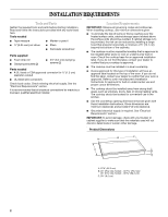
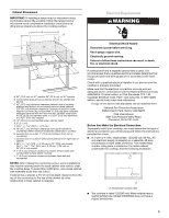
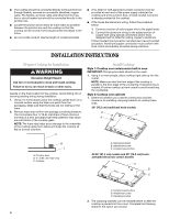
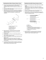
Cabinet Dimensions IMPORTANT: If installing a range hood or microwave hood combination above the cooktop, follow the range hood or microwave hood combination installation instructions for dimensional clearances above the cooktop surface. A D Electrical Requirements WARNING C B L F G E H I K J A. 30" (76.2 cm) on 30" models; 36" (91.4 cm) on 36" models B. Combustible area above countertop (shown by dashed box above) C. 30" (76.2 cm) minimum clearance between top of cooktop platform and bottom of uncovered wood or metal cabinet (24" [61 cm] minimum clearance if bottom of wood or metal cabinet is covered by not less than ¹⁄₄" [0.6 cm] flame retardant millboard covered with not less than No. 28 MSG sheet steel, 0.015" [0.04 cm] stainless steel, or 0.024" [0.06 cm] aluminum or 0.020" [0.05 cm] copper) D. 13" (33 cm) recommended upper cabinet depth E. 2" (5.1 cm) F. 20 52.0 +/- 0.16 cm) G. 18" (45.7 cm) minimum clearance from upper cabinet to countertop within minimum horizontal clearances to cooktop H. Junction box or outlet: 7" (17.8 cm) minimum from top of countertop I. Junction box or outlet: 9" (23.0 cm) maximum from right side of cabinet J. 29 74.9 +/- 0.16 cm) on 30" (76.2 cm) models 35 90.2 cm + 0.16 cm/- 2.38 cm) on 36" (91.4 cm) models K. 1" (2.5 cm) minimum distance to nearest left and right side combustible surface above cooktop L. 1" (2.5 cm) minimum clearance between back wall and countertop NOTES: After making the countertop cutout, some installations may require notching down the base cabinet side walls to clear the cooktop base. To avoid this modification, use a base cabinet with sidewalls wider than the cutout. If cabinet has a drawer, a 5½" (14.0 cm) depth clearance from the top of the countertop to the top of the drawer (or other obstruction) in base cabinet is required. Electrical Shock Hazard Disconnect power before servicing. Use 8 gauge copper wire. Electrically ground cooktop. Failure to follow these instructions can result in death, fire, or electrical shock. If codes permit and a separate ground wire is used, it is recommended that a qualified electrical installer determine that the ground path and wire gauge are in accordance with local codes. Check with a qualified electrical installer if you are not sure the cooktop is properly grounded. Make sure that the electrical connection and wire size are adequate and in conformance with the National Electrical Code, ANSI/NFPA 70-latest edition or CSA Standards C22.1-94, Canadian Electrical Code, Part 1 and C22.2 No. O-M91-latest edition, and all local codes and ordinances. A copy of the above code standards can be obtained from: National Fire Protection Association Batterymarch Park, Quincy, MA 02269 CSA International 8501 East Pleasant Valley Road Cleveland, OH 44131-5575 Before You Make the Electrical Connection: To properly install your cooktop, you must determine the type of electrical connection you will be using and follow the instructions provided for it here. ■ A 3-wire or 4-wire, single phase, 120/240 volt, 60-Hz., AC only electrical supply is required on a separate, 40-amp circuit fused on both sides of the line. The model/serial number rating plate is located on the metal cabinet underneath the cooktop. See the following illustration. A A. Model/serial number plate ■ The cooktop is rated 120/240 volt. Most models have a neutral (white) wire. Model W5CE3024 does not have a neutral (white) wire. 3
-
 1
1 -
 2
2 -
 3
3 -
 4
4 -
 5
5 -
 6
6 -
 7
7 -
 8
8 -
 9
9 -
10
-
11
-
12
-
13
-
14
-
15
-
16
 |
 |
