Whirlpool G7CE3034XB Installation Instructions - Page 4
Installation Instructions
 |
View all Whirlpool G7CE3034XB manuals
Add to My Manuals
Save this manual to your list of manuals |
Page 4 highlights
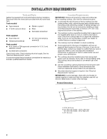
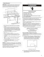
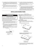
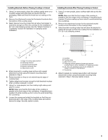
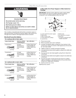
■ The cooktop should be connected directly to the junction box through flexible, armored or nonmetallic sheathed, copper cable. The flexible, armored cable extending from the fuse box or circuit breaker box should be connected directly to the junction box. ■ Locate the junction box to allow as much slack as possible between the junction box and the cooktop so that the cooktop can be moved if servicing becomes necessary in the future. ■ Do not cut the conduit. Use the length of conduit provided. ■ A UL listed or CSA approved conduit connector must be provided at each end of the power supply cable (at the cooktop and at the junction box). A listed conduit connector is already provided at the cooktop. ■ If the house has aluminum wiring, follow the procedure below: 1. Connect a section of solid copper wire to the pigtail leads. 2. Connect the aluminum wiring to the added section of copper wire using special connectors and/or tools designed and UL listed for joining copper to aluminum. Follow the electrical connector manufacturer's recommended procedure. Aluminum/copper connection must conform with local codes and industry accepted wiring practices. INSTALLATION INSTRUCTIONS Prepare Cooktop for Installation WARNING Excessive Weight Hazard Use two or more people to move and install cooktop. Failure to do so can result in back or other injury. Decide on the final location for the cooktop. Avoid drilling into or severing existing wiring during installation. 1. Using 2 or more people, place the cooktop upside down on a covered surface using the foam end posts from the packaging. Make sure that the knobs are not resting on the foam. 2. Remove foam strip roll from the package containing literature. The roll contains four ¼" (0.64 cm) strips of foam. Remove one strip at a time and apply foam strip adhesive-side down around bottom of the cooktop glass. NOTE: The foam strip helps avoid damage to the underside of the cooktop glass from debris and helps the cooktop sit flat on uneven counters. A Install Cooktop Style 1: Cooktop over undercounter built-in oven IMPORTANT: Clamping brackets should not be used. 1. Using 2 or more people, place cooktop right side up into the cutout. NOTE: Make sure that the front edge of the cooktop is parallel to the front edge of the countertop. If repositioning is needed, lift entire cooktop up from cutout to avoid scratching the countertop. Style 2: Cooktop over cabinets 1. Determine whether your cabinet construction provides clearance for installing clamping brackets at cooktop base ends. 30" (76.2 cm) traditional knob models B C A B C A. Cooktop base B. ¼" (0.64 cm) Foam strip C. Cooktop A. Clamping bracket B. Attachment screw C. Cooktop base bottom All 36" (91.4 cm) models and 30" (76.2 cm) touchactivated electronic control models A B C A. Cooktop base bottom B. Attachment screw C. Clamping bracket 2. The clamping brackets can be installed before or after the cooktop is placed into the cutout. Complete the following steps for the option you choose. 4
-
 1
1 -
 2
2 -
 3
3 -
 4
4 -
 5
5 -
 6
6 -
 7
7 -
 8
8 -
 9
9 -
 10
10 -
11
-
12
-
13
-
14
-
15
-
16
 |
 |
