Whirlpool GBS277PDQ Installation Instructions - Page 3
Electrical Requirements, Installation Steps, A. Preparation - model
 |
View all Whirlpool GBS277PDQ manuals
Add to My Manuals
Save this manual to your list of manuals |
Page 3 highlights
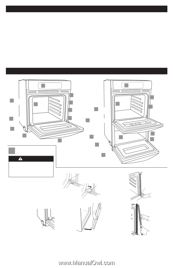
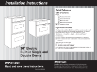
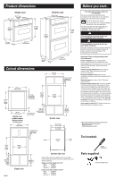
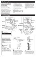
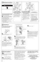
Electrical requirements If codes permit and a separate grounding wire is used, it is recommended that a qualified electrician determine that the grounding path and wire gauge is in accordance with local codes. Do Not ground to a gas pipe. Check with a qualified electrician if you are not sure oven is properly grounded. Do Not have a fuse in the neutral or grounding circuit. Oven must be connected to the proper electrical voltage and frequency as specified on the model/serial rating plate. (The model/serial rating plate is located on the oven door or on the oven frame.) ࠜ Models rated from 7.3 to 9.6 kW at 240 volts (5.5 to 7.2 kW at 208 volts) require a separate 40-ampere circuit. Models rated at 7.2 kW and below at 240 volts (5.4 kW and below at 208 volts) require a separate 30-ampere circuit. ࠜ A time-delay fuse or circuit breaker is recommended. ࠜ Connect directly to the fused disconnect (or circuit breaker box) through flexible, armored or non-metallic sheathed, copper cable (with grounding wire). ࠜ Flexible armored cable from appliance should be connected directly to junction box. ࠜ Fuse both sides of the line. ࠜ A U.L.-listed conduit connector must be provided at the junction box. ࠜ Do Not cut the conduit. Wire sizes and connections must conform with the rating of the appliance and to the requirements of the National Electrical Code, ANSI/NFPA 70 - latest edition (*, See Page 1) and all local codes and ordinances. Installation Steps If the house has aluminum wiring, follow the procedure below. a.) Connect the aluminum wiring to the copper wire using special connectors designed and Underwriters Laboratories-listed for joining copper to aluminum. Follow the electrical connector manufacturer's recommended procedure. b.) Aluminum/copper connection must conform with local codes and industry-accepted wiring practice. D Check oven operation. D Check oven operation. C Grasp oven frame to lift oven. A Remove oven racks. B power supply cable C Use screws to attach oven to cabinet. C Reattach side trim pieces. A Remove side trim. C Grasp oven frame to lift oven. A Remove trim screws. C Use screws to attach oven to cabinet. A Remove oven racks. C Reattach side trim pieces. A Remove side trim. C Remove shipping feet. C Replace oven door. A Remove oven door. A Preparation WARNING Excessive Weight Hazard Use two or more people to move and install oven. Failure to follow this instruction can result in back or other injury. Important: Use both hands to remove oven doors. Do Not use handle or any portion of the front frame or trim for lifting. Before moving oven across floor, check that oven is on shipping base or slide oven onto cardboard or hardboard. Do Not remove shipping feet at the front lower corners of oven. B power supply cable C Remove shipping feet. A Remove oven racks. C Replace oven doors. latch on the hinge in locked position - door free to open and close latch on the hinge in unlocked position - door ready for removal A Remove trim screws. A Remove oven doors. Remove trim screw. Pull trim out. 1. Turn power supply off. Move oven close to final position. • Remove and discard shipping materials, tape and protective film from Do Not the oven. Do Not remove remove shipping base shipping feet. or shipping feet at the front lower corners of oven. The shipping feet will protect the lower oven trim until oven is inserted into cabinet. • Remove and set aside racks and other parts from inside oven. 2. Completely open oven door. In both back corners of the door you will see door latches in the locked position. Rotate both latches forward to the unlocked position. Grasp outside edges of door with both hands. • Begin closing door, at the moment the door stops closing, lift and pull door toward you. • Set door aside on a protective surface. Pull top of trim down. 3. Remove trim screws attaching right and left side trim to oven. Grasp the bottom end of trim and pull away from oven. Slide top end of trim downward to remove trim from oven. Take care not to scratch other surfaces with ends of trim. Set trim and screws aside on protected surface. Page 2
-
 1
1 -
 2
2 -
 3
3 -
 4
4 -
 5
5
 |
 |