Whirlpool GEW9868KQ Installation Instructions - Page 3
the exhaust - manual
 |
View all Whirlpool GEW9868KQ manuals
Add to My Manuals
Save this manual to your list of manuals |
Page 3 highlights
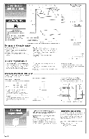
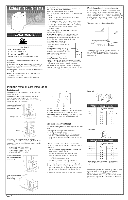
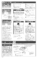
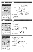
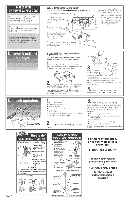
Fire Hazard Use a heavy metal vent. Do not use a piastB vent, Do not use a metal foi[ vent. Faiture to do so can result in death or fire. Important: Observe alt governing ¢odes and ordinances. mtis recommended that you exhaust your dryer to the outside for best performance. Moisture and lint indoors may cause: * Lint to gather around the dryer where it can be fuel for a fire. Moisture damage to woodwork, furniture, paint, wallpaper, carpet, etc. Housecleaning problems and heakh problems. Dura Safe TM venting products are recommended and are available from your deaJero Fourdnch diameter vent must be used. Use a heavy metal vent. Do Not use plastic or metal foil vent. o Do Not use non°meta[ flexible vent, or exhaust hoods with magnetic Iatches. Do Not exhaust dryer into a chimney, wail, ceiling, furnace, coM air vent, duct, concealed space, attic or craw[ space, or any other vent used for venting. Do Not install flexible vent in enclosed walls, ceilings or floors. Rigid metal vent is recommended crushing and kinking. to prevent Flexible metal vent must be fully extended and supported when the dryer is in its final position. Remove excess flexible vent to avoid sagging and kinking that may result in reduced air flow. An exhaust hood should cap the exhaust vent to prevent rodents and insects from entering the home. Exhaust outlet hood must be at least 12 inches from the ground or any object that may be in the path of the exhaust (such as flowers, rocks or bushes, etc.). If using an existing exhaust system, clean lint from entire length of system and make sure exhaust hood is not plugged with lint. Replace any plastic or metal foil vent with rigid metal or flexible metal vent. Use damps to seal all joints. Do Not use duct tape, screws or other fastening devices that extend into the interior of the vent to secure vent. M@iie heme [nstaiJatienrequirements If codes permit, this appliance [s suitable for mobile home installations. The instai[at[on of the dryer must conform to Manufactured Home Construction and Safety Standard, Title 24 CFR, Part 3280 (formerly the Federal Standard for Mobile Homes Construction and Safety, Title 24, HUD Part 280) or latest edition. The dryer must be exhausted outside. outside waJ[ ,,oor kL enclosed area The exhaust vent must be securely fastened to a non-combustible protion of the mobile home structure and must not terminate beneath the mobile home, Planthe exhaust ventinstaliatien Beute the vent The exhaust outlet is located at the center of the rear of the dryer. The exhaust vent can be routed up, down, [eft, right or straight out the back of the dryer, See "Recessed area/closet installation" section, Panel A, for general space requirements. better exhaust air flow Preferred-- rear of the dryer. straight back offset_ This dwer may be converted to exhaust out the right or left side or through the bottom. To convert the dryel, the folIowing kits are available from your dealer: Exhaust Exhaust Exhaust Exhaust Kit No. 279818 Kit No. 279819 Kit No. 279925 Kit No. 279969 (white) (almond) (biscuit) (silver) Typical installations for [eft or right side exhausting. Typical installations for bottom exhausting. Select the route that will provide the straightest and most direct path outdoors. Plan the installation to use the fewest number of elbows and turns. When using eBbows or making turns, allow as much room as possible, Bend vent gradually to avoid kinking, Determine exhaust vent Jength The maximum upon: length of the exhaust system depends the type of vent (rigid or flexible metal). the number of elbows used. • side or bottom exhaust. Side or bottom exhaust adds a 90 ° turn inside the dryer, To determine maximum exhaust length, add one 90 ° turn to the chart. 1. See the exhaust vent length chart that matches your type hood for the maximum vent lengths you can use, Do not use vent runs longer than specified in exhaust vent length charts. Exhaust systems Ionger than specified will: -- accumulate lint creating a potential fire hazard. -- shorten the Iife of the dryer. -- reduce performance, resulting in Ionger drying times and increased energy usage. 2_ Determine the number of elbows you will need. 3. In the column listing the type of metal vent you are using (rigid or flexible), find the maximum length of metal vent on the same line as the number of elbows. Determine the number of 4" clamps you will need. Number of 90 ° elbows 0 1 2 g 4 ,Maximum length of 4 diameter metal vent Rigid 64 ft. 54 ft. 44 ft. 35 ft. 27 ft. Flexible (fully extended) 36 ft. 31 ft. 27 ft. 25 ft. 23 ft. Acceptable -- __2-1/2" Number of 90 ° elbows 0 1 2 3 4 ,Maximum length of 4 diameter metal vent Rigid 58 ft. 48 ft. 38 ft. 29 ft. 21 ft. Flexible (fully extended) 28 ft. 23 ft. 19 ft. 17 ft, 15 ft. The maximum length using a 2" x 6" rectangMar vent with 2 elbows and a 2-1/2 exhaust hood is 8 ft. For exhaust systems not covered by exhaust vent length charts (such as multiple unit hookups, plenums, and poweroassist fans), see Service Manual, Part No. 60319Z (To purchase the Service Manual, see your Use and Care Guide for a toll-free telephone number.) PaneJ B
-
 1
1 -
 2
2 -
 3
3 -
 4
4 -
 5
5 -
 6
6 -
 7
7
 |
 |
