Whirlpool LDR3822P Owners Manual 1 - Page 9
Install Vent System, Connect Vent Vented Models Only
 |
View all Whirlpool LDR3822P manuals
Add to My Manuals
Save this manual to your list of manuals |
Page 9 highlights
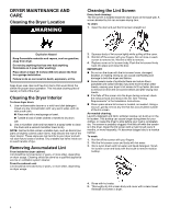
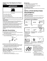
Alternate installations for close clearances Venting systems come in many varieties. Select the type best for your installation. Two close-clearance installations are shown. NOTE: The following kits for close-clearance alternate installations are available for purchase. Refer to Quick Start Guide for contact information. Install Vent System 1. Remove the wire exhaust guard Before installing the vent system, be sure to remove the wire exhaust guard that is located at the exhaust outlet. 2. Install exhaust hood A. Over-the-top installation (also available with one offset elbow) B. Periscope installation Special provisions for mobile home installations: Exhaust vent must be securely fastened to a noncombustible portion of the mobile home and must not terminate beneath the mobile home. Terminate exhaust vent outside. Determine vent path: � Select route that will provide straightest and most direct path outdoors. � Plan installation to use fewest number of elbows and turns. � When using elbows or making turns, allow as much room as possible. � Bend vent gradually to avoid kinking. � Use as few 90° turns as possible. Determine vent length and elbows needed for best drying performance: � Use following "Vent System Chart" to determine type of vent material and hood combinations acceptable to use. NOTE: Do not use vent runs longer than those specified in "Vent System Chart." Exhaust systems longer than those specified will: � Shorten life of dryer. � Reduce performance, resulting in longer drying times and increased energy usage. The "Vent System Chart" provides venting requirements that will help achieve best drying performance. Vent System Chart Number of 90° turns or elbows 0 Type of vent Rigid metal Box/louvered Angled hoods hoods 36 ft. (11 m) 26 ft. (7.9 m) 1 Rigid metal 26 ft. (7.9 m) 16 ft. (4.9 m) 2 Rigid metal 16 ft. (4.9 m) 6 ft. (1.8 m) Install exhaust hood and use caulking compound to seal exterior wall opening around exhaust hood. 3. Connect vent to exhaust hood Vent must fit over the exhaust hood. Secure vent to exhaust hood with 4" (102 mm) clamp. Run vent to dryer location using straightest path possible. Avoid 90° turns. Use clamps to seal all joints. Do not use duct tape, screws, or other fastening devices that extend into interior of vent to secure vent, because they can catch lint. Connect Vent (Vented Models Only) 1. Connect vent to exhaust outlet Using a 4" (102 mm) clamp, connect vent to exhaust outlet in dryer. If connecting to existing vent, make sure vent is clean. Dryer vent must fit over dryer exhaust outlet and inside exhaust hood. Check that vent is secured to exhaust hood with a 4" (102 mm) clamp. 9
-
 1
1 -
2
-
3
-
 4
4 -
 5
5 -
 6
6 -
 7
7 -
 8
8 -
 9
9 -
 10
10 -
 11
11 -
 12
12 -
 13
13 -
 14
14 -
15
-
16
-
17
-
18
-
19
-
20
-
21
 |
 |
