Whirlpool WED9371YL Installation Guide - Page 16
Install Vent System
 |
View all Whirlpool WED9371YL manuals
Add to My Manuals
Save this manual to your list of manuals |
Page 16 highlights
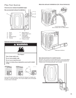
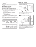
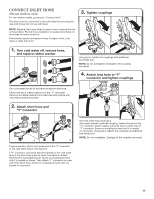
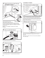
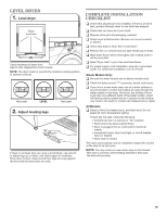
Determine vent path: ■■Select route that will provide straightest and most direct path outdoors. ■■Plan installation to use fewest number of elbows and turns. ■■When using elbows or making turns, allow as much room as possible. ■■Bend vent gradually to avoid kinking. ■■Use as few 90° turns as possible. Determine vent length and elbows needed for best drying performance: ■■Use the following Vent System Chart to determine type of vent material and hood combinations acceptable to use. NOTE: Do not use vent runs longer than those specified in Vent system chart. Exhaust systems longer than those specified will: ■■Shorten life of dryer. ■■Reduce performance, resulting in longer drying times and increased energy usage. The Vent System Chart provides venting requirements that will help achieve best drying performance. NOTE: Side and bottom exhaust installation have a 90° turn inside the dryer. To determine maximum exhaust length, add one 90° turn to the chart. Install Vent System 1. Install exhaust hood 12" min. (305 mm) 12" min. (305 mm) Install exhaust hood and use caulking compound to seal exterior wall opening around exhaust hood. 2. Connect vent to exhaust hood Number of 90° elbows Vent System Chart Type of vent Box/louvered hoods Angled hoods 0 Rigid metal 64 ft. (20 m) 58 ft. (17.7 m) 1 Rigid metal 54 ft. (16.5 m) 48 ft. (14.6 m) 2 Rigid metal 44 ft. (13.4 m) 38 ft. (11.6 m) 3 Rigid metal 35 ft. (10.7 m) 29 ft. (8.8 m) 4 Rigid metal 27 ft. (8.2 m) 21 ft. (6.4 m) Vent must fit over the exhaust hood. Secure vent to exhaust hood with 4" (102 mm) clamp. Run vent to dryer location using straightest path possible. Avoid 90° turns. Use clamps to seal all joints. Do not use duct tape, screws, or other fastening devices that extend into interior of vent to secure vent, because they can catch lint. 16
-
 1
1 -
2
-
3
-
4
-
5
-
6
-
7
-
8
-
9
-
10
-
 11
11 -
 12
12 -
 13
13 -
 14
14 -
 15
15 -
 16
16 -
 17
17 -
 18
18 -
 19
19 -
 20
20
 |
 |
