Whirlpool WFG320M0BS Installation Guide
Whirlpool WFG320M0BS Manual
 |
View all Whirlpool WFG320M0BS manuals
Add to My Manuals
Save this manual to your list of manuals |
Whirlpool WFG320M0BS manual content summary:
- Whirlpool WFG320M0BS | Installation Guide - Page 1
3 Tools and Parts 3 Location Requirements 4 Electrical Requirements 5 Gas Supply Requirements 6 INSTALLATION INSTRUCTIONS 7 Unpack Range 7 Install Anti-Tip Bracket 7 Make Gas Connection 8 Verify Anti-Tip Bracket Is Installed and Engaged 9 Level Range 10 Electronic Ignition System 10 - Whirlpool WFG320M0BS | Installation Guide - Page 2
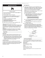
follow the "What to do if you smell gas" instructions. IMPORTANT: Do not install a ventilation system that blows air downward toward this gas cooking appliance. This type of ventilation system may cause ignition and combustion problems with this gas cooking appliance resulting in personal injury or - Whirlpool WFG320M0BS | Installation Guide - Page 3
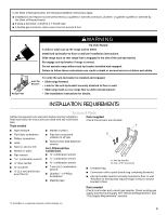
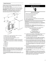
or wall. • Slide range back so rear range foot is under anti-tip bracket. • See installation instructions for details. INSTALLATION REQUIREMENTS Tools and Parts Gather the required tools and parts before starting installation. Parts supplied Read and follow the instructions provided with any - Whirlpool WFG320M0BS | Installation Guide - Page 4
rating plate. The model/serial rating plate is located on the left side of the bottom of the broiler. Mobile Home - Additional Installation Requirements The installation of this range must conform to the Manufactured Home Construction and Safety Standard, Title 24 CFR, Part 3280 (formerly the - Whirlpool WFG320M0BS | Installation Guide - Page 5
oven frame must extend beyond cabinet fronts by ½" (13.0 mm) minimum. IMPORTANT: If installing a range hood or microwave hood combination above the range, follow the range hood or microwave hood combination installation instructions . This range is equipped with an electronic ignition system that - Whirlpool WFG320M0BS | Installation Guide - Page 6
service technician. No attempt shall be made to convert the appliance from the gas specified on the model/serial rating plate for use with a different gas without consulting the serving gas supplier. See "Gas Conversions" section. C A. Gas supply line B. Shutoff valve "open" position C. To range - Whirlpool WFG320M0BS | Installation Guide - Page 7
injury. 1. Do not use oven door handle to lift or move the range. 2. Remove shipping materials, tape and film from range. Keep cardboard bottom and foam support under range. 3. Remove oven racks and parts package from inside oven and broiler cavity. 4. To place range on its back, take 4 cardboard - Whirlpool WFG320M0BS | Installation Guide - Page 8
to continue installing the range using the following installation instructions. A B D C E F G H A. Pressure regulator connection fitting B. Use pipe-joint compound. C. Adapter D. Flexible connector E. Adapter F. Use pipe-joint compound. G. Manual shutoff valve H. ½" or ¾" gas pipe 8 - Whirlpool WFG320M0BS | Installation Guide - Page 9
"ON" position. If the range does not work, verify that the valve is in the "ON" position. 3. Open the manual shutoff valve in the gas supply line. The valve is open when the handle is parallel to the gas pipe. A B 5. Remove cooktop burner caps and grates from parts package. Align notches in burner - Whirlpool WFG320M0BS | Installation Guide - Page 10
" section of the User Instructions, to contact service. Level Range 1. Place a standard flat rack in oven. 2. Place level on the rack and check levelness of the range, first side to side; then front to back. Low Med Electronic Ignition System Initial lighting and gas flame adjustments Cooktop and - Whirlpool WFG320M0BS | Installation Guide - Page 11
turned from "HIGH" to "LOW." Turn right to decrease flame height. light. 2. Press the START/ENTER pad. ■ The oven burner should light in 20-40 seconds; this delay is normal. The oven valve requires a certain time before it will open and allow gas to flow. To avoid damaging the hot surface igniter - Whirlpool WFG320M0BS | Installation Guide - Page 12
oven. See the Use and Care Guide or User Instructions for specific instruction on range operation. ■ Range is plugged into a grounded 3 prong outlet. ■ Gas pressure regulator shutoff valve is in the "on" position. ■ Electrical supply is connected. ■ See "Troubleshooting" in the Use and Care Guide - Whirlpool WFG320M0BS | Installation Guide - Page 13
NOTE: Be sure sealing washer remains in the same position. A A B A. Burner cap B. Burner 2. Locate LP gas orifice spuds for top burners in the bag containing literature included with the range. One LP gas spud is stamped "88 (Yellow/Black)," two are stamped "116 (Yellow/Orange)," and one is stamped - Whirlpool WFG320M0BS | Installation Guide - Page 14
. 8. Reinstall oven racks, oven tray and flame spreader. Complete Conversion 1. Refer to the "Make Gas Connection" section for properly connecting the range to the gas supply. 2. Turn the manual shutoff valve in the gas supply line to the open position. 3. Refer to the "Electronic Ignition System - Whirlpool WFG320M0BS | Installation Guide - Page 15
Make sure sealing washer remains in the same position. A A B A. Burner cap B. Burner 2. Locate the Natural gas orifice spuds for top burners in the bag containing literature included with the range. Two Natural gas spuds are stamped "194 (Black/White)," one is stamped "155 (Red/Brown)," and one is - Whirlpool WFG320M0BS | Installation Guide - Page 16
. 8. Reinstall oven racks, oven tray and flame spreader. Complete Conversion 1. Refer to the "Make Gas Connection" section for properly connecting the range to the gas supply. 2. Turn the manual shutoff valve in the gas supply line to the open position. 3. Refer to the "Electronic Ignition System
-
 1
1 -
 2
2 -
 3
3 -
 4
4 -
 5
5 -
 6
6 -
 7
7 -
8
-
9
-
10
-
11
-
12
-
13
-
14
-
15
-
16
 |
 |

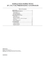
INSTALLATION INSTRUCTIONS
30" (76.2 CM) FREESTANDING GAS RANGES
Table of Contents
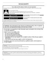
RANGE SAFETY
...................................................................................
2
INSTALLATION REQUIREMENTS
.....................................................
3
Tools and Parts
..................................................................................
3
Location Requirements
.....................................................................
4
Electrical Requirements
.....................................................................
5
Gas Supply Requirements
................................................................
6
INSTALLATION INSTRUCTIONS
.......................................................
7
Unpack Range
...................................................................................
7
Install Anti-Tip Bracket
......................................................................
7
Make Gas Connection
.......................................................................
8
Verify Anti-Tip Bracket Is Installed and Engaged
.............................
9
Level Range
.....................................................................................
10
Electronic Ignition System
...............................................................
10
Complete Installation
.......................................................................
12
GAS CONVERSIONS
.........................................................................
12
LP Gas Conversion
..........................................................................
12
Complete Conversion
......................................................................
14
Natural Gas Conversion
..................................................................
14
Complete Conversion
......................................................................
16
W10620413D
IMPORTANT:
Save for local inspector's use.
Installer:
Leave installation instructions with the homeowner.
Homeowner:
Keep installation instructions for future reference.