Whirlpool WFG361LVS Installation Instructions - Page 9
Make Gas Connection - gas range instructions
 |
UPC - 883049139159
View all Whirlpool WFG361LVS manuals
Add to My Manuals
Save this manual to your list of manuals |
Page 9 highlights
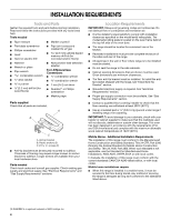
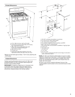
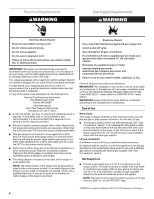
5. To mount anti-tip bracket to wood floor, drill two ¹⁄₈" (3.2 mm) holes at the positions marked on the bracket template. Remove template from floor. Make Gas Connection WARNING To mount anti-tip bracket to concrete or ceramic floor, use a 4.8 mm) masonry drill bit to drill 2 holes at the positions marked on the bracket template. Remove template from floor. Tap plastic anchors into holes with a hammer. 6. Align anti-tip bracket holes with holes in floor. Fasten anti-tip bracket with screws provided. Explosion Hazard Use a new CSA International approved gas supply line. Install a shut-off valve. Securely tighten all gas connections. If connected to LP, have a qualified person make sure gas pressure does not exceed 14" (36 cm) water column. Examples of a qualified person include: licensed heating personnel, authorized gas company personnel, and authorized service personnel. Failure to do so can result in death, explosion, or fire. Depending on the thickness of your flooring, longer screws may be necessary to anchor the bracket to the subfloor. Longer screws are available from your local hardware store. 7. Move range close enough to opening to allow for final electrical connection. Remove shipping base, cardboard or hardboard from under range. 8. Move range into its final location making sure rear leveling leg slides into anti-tip bracket. 9. If installing the range in a mobile home, you must secure the range to the floor. Any method of securing the range is adequate as long as it conforms to the standards in the "Location Requirements" section. 10. Continue installing your range using the following installation instructions. Typical rigid pipe connection A combination of pipe fittings must be used to connect the range to the existing gas line. Your connections may be different, according to the supply line type, size and location. 1. Apply pipe-joint compound made for use with LP gas to all pipe thread connections. 2. Using a pipe wrench to tighten, connect the gas supply to the range. B C D A F E J A. Gas pressure regulator B. 90° elbow (must have ½" male pipe thread) C. Nipple D. Union E. Black iron pipe I H G F. Manual gas shutoff valve G. ½" or ¾" gas pipe H. Nipple I. Union J. 90° elbow Typical flexible connection 1. Apply pipe-joint compound made for use with LP gas to the smaller thread ends of the flexible connector adapters (see B and G in the following illustration). 2. Attach one adapter to the gas pressure regulator and the other adapter to the gas shutoff valve. Tighten both adapters. 9
-
 1
1 -
2
-
3
-
 4
4 -
 5
5 -
 6
6 -
 7
7 -
 8
8 -
 9
9 -
 10
10 -
 11
11 -
 12
12 -
 13
13 -
 14
14 -
15
-
16
-
17
-
18
-
19
-
20
 |
 |
