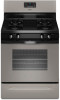
Whirlpool WFG510S0AD Installation Guide
Whirlpool WFG510S0AD Manual
 |
View all Whirlpool WFG510S0AD manuals
Add to My Manuals
Save this manual to your list of manuals |
Whirlpool WFG510S0AD manual content summary:
- Whirlpool WFG510S0AD | Installation Guide - Page 1
CM) FREESTANDING GAS RANGES Table of Contents RANGE SAFETY 2 INSTALLATION REQUIREMENTS 3 Tools and Parts 3 Location Requirements 3 Electrical Requirements 5 Gas Supply Requirements 5 INSTALLATION INSTRUCTIONS 7 Unpack Range 7 Install Anti-Tip Bracket 7 Make Gas Connection 8 Verify Anti-Tip - Whirlpool WFG510S0AD | Installation Guide - Page 2
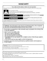
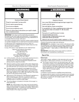
. We have provided many important safety messages in this manual and on your appliance. Always read and obey all safety messages. This is instructions. • If you cannot reach your gas supplier, call the fire department. - Installation and service must be performed by a qualified installer, service - Whirlpool WFG510S0AD | Installation Guide - Page 3
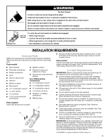
so rear range foot is under anti-tip bracket. • See installation instructions for details. INSTALLATION REQUIREMENTS Tools and Parts Gather the required tools and parts before starting installation. Read and follow the instructions provided with any tools listed here. Tools needed ■ Tape measure - Whirlpool WFG510S0AD | Installation Guide - Page 4
Title 24, HUD Part 280). When such standard is not applicable, use the Standard for Manufactured Home Installations, ANSI A225.1/NFPA 501A or with local codes. Mobile home installations require: ■ When this range is installed in a mobile home, it must be secured according to the instructions in this - Whirlpool WFG510S0AD | Installation Guide - Page 5
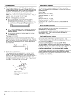
water column. Examples of a qualified person include: licensed heating personnel, authorized gas company personnel, and authorized service be conducted according to the manufacturer's instructions. Type of Gas Natural gas: service technician. No attempt shall be made to convert the appliance from - Whirlpool WFG510S0AD | Installation Guide - Page 6
the female pipe threads of the inlet to the appliance pressure regulator. ■ Do not kink or damage : The supply line must be equipped with a manual shutoff valve. This valve should be located in the for testing regulator must be at least 1" water column pressure above the manifold pressure shown on - Whirlpool WFG510S0AD | Installation Guide - Page 7
INSTALLATION INSTRUCTIONS Unpack Range WARNING Excessive Weight Hazard Use two or more people to move and install range. Failure to do so can result in back or other injury. 1. Remove shipping materials, tape and film from range. 2. Remove oven racks and parts package from inside oven. 3. Do not - Whirlpool WFG510S0AD | Installation Guide - Page 8
the following installation instructions. Explosion Hazard water column. Examples of a qualified person include: licensed heating personnel, authorized gas company personnel, and authorized service C. Nipple D. Union E. Black iron pipe I HG F. Manual gas shutoff valve G. ½" or ¾" gas pipe H. Nipple - Whirlpool WFG510S0AD | Installation Guide - Page 9
valve shown in the "on" position 2. Open the manual shutoff valve in the gas supply line. The valve is Do not use an extension cord. Failure to follow these instructions can result in death, fire, or electrical shock. 5. cooktop burner caps and grates from parts package. Burner caps should be level - Whirlpool WFG510S0AD | Installation Guide - Page 10
range without anti-tip bracket installed and engaged. Please reference the "Assistance or Service" section of the Use and Care Guide, or the cover or "Warranty" section of the User Instructions, to contact service. Level Range Determine if you have AquaLift™ Technology or Steam Clean by referring - Whirlpool WFG510S0AD | Installation Guide - Page 11
within 8 seconds. Under certain conditions, it may take the burner up to 50 to 60 seconds to light. Refer to the Use and Care Guide or User Instructions for proper operation of the oven controls. Adjust Oven Broil Burner Flame (if needed) Look through oven window to check broil burner for proper - Whirlpool WFG510S0AD | Installation Guide - Page 12
If flame needs to be adjusted: 1. Loosen the lock screw on the air shutter located at the rear of the broil burner. 2. Adjust the air shutter as needed. 3. Tighten lock screw. To Replace: 1. Align the forward drawer notches with the notches in the drawer glides on both sides. Place the rear - Whirlpool WFG510S0AD | Installation Guide - Page 13
and tight, or circuit breaker has not tripped. ■ Range is plugged into a grounded 3 prong outlet. ■ Electrical supply is connected. ■ See "Troubleshooting" in the Use and Care Guide or User Instructions. 8. When the range has been on for 5 minutes, check for heat. If the range is cold, turn off the - Whirlpool WFG510S0AD | Installation Guide - Page 14
water column. Examples of a qualified person include: licensed heating personnel, authorized gas company personnel, and authorized service instructions can result in death or serious burns to children and adults. 1. Turn the manual shutoff valve to the closed position. B A C A. To range B. Manual - Whirlpool WFG510S0AD | Installation Guide - Page 15
3. Remove plastic cover from gas pressure regulator cap. 4. Turn gas pressure regulator cap counterclockwise with a ⁵⁄₈" combination wrench to remove. NOTE: Do not remove the spring beneath the cap. Side view before A 3. Apply masking tape to the end of a 7 mm nut driver to help hold the gas - Whirlpool WFG510S0AD | Installation Guide - Page 16
To Convert Oven Bake Burner (Natural Gas to LP Gas) 1. Remove the oven racks. 2. Remove 2 screws at the rear of the oven bottom. 3. Lift the rear of the oven bottom up and back until the front of the panel is away from the front frame. Remove from oven and set it aside on a covered surface. A 8. - Whirlpool WFG510S0AD | Installation Guide - Page 17
not as distinct as the inner cone. LP gas flames have a slightly yellow tip. 3. Refer to "Complete Installation" in the "Installation Instructions" section of this manual to complete this procedure. NOTE: Make sure to save the orifices that have just been replaced in the conversion. Tip Over Hazard - Whirlpool WFG510S0AD | Installation Guide - Page 18
the top left side of the oven door for proper sizing of spuds for each burner location. 5. Place LP gas orifice spuds in plastic parts bag for future use and keep with package containing literature. 6. Replace the burner base using both screws. 7. Replace burner cap. 8. Repeat steps 1-7 for the - Whirlpool WFG510S0AD | Installation Guide - Page 19
4. Remove 2 screws from the front tabs of the flame spreader. Lift front of the flame spreader and pull forward to remove tabs from rear of oven and set it aside on a covered surface. B A A. Screws B. Flame spreader 5. Remove 2 screws from the bake burner. 6. Slide the front of the bake burner to - Whirlpool WFG510S0AD | Installation Guide - Page 20
broil burner flame is very important. Natural gas flames do not have yellow tips. 3. Refer to "Complete Installation" in the "Installation Instructions" section of this manual to complete this procedure. NOTE: Make sure to save the orifices that have just been replaced in the conversion. W10403809B
-
 1
1 -
 2
2 -
 3
3 -
 4
4 -
 5
5 -
 6
6 -
 7
7 -
8
-
9
-
10
-
11
-
12
-
13
-
14
-
15
-
16
-
17
-
18
-
19
-
20
 |
 |

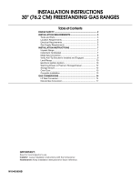
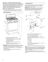
INSTALLATION INSTRUCTIONS
30" (76.2 CM) FREESTANDING GAS RANGES
Table of Contents
RANGE SAFETY
.............................................................................
2
INSTALLATION REQUIREMENTS
...............................................
3
Tools and Parts
............................................................................
3
Location Requirements
...............................................................
3
Electrical Requirements
...............................................................
5
Gas Supply Requirements
..........................................................
5
INSTALLATION INSTRUCTIONS
.................................................
7
Unpack Range
.............................................................................
7
Install Anti-Tip Bracket
................................................................
7
Make Gas Connection
.................................................................
8
Verify Anti-Tip Bracket Is Installed and Engaged
.......................
9
Level Range
...............................................................................
10
Electronic Ignition System
.........................................................
10
Warming Drawer or Premium Storage Drawer
.........................
12
Storage Drawer
..........................................................................
12
Oven Door
..................................................................................
13
Complete Installation
.................................................................
13
GAS CONVERSIONS
...................................................................
14
LP Gas Conversion
....................................................................
14
Natural Gas Conversion
............................................................
17
W10403809B
IMPORTANT:
Save for local inspector's use.
Installer:
Leave installation instructions with the homeowner.
Homeowner:
Keep installation instructions for future reference.