Whirlpool WFG510S0AD Use & Care Guide - Page 5
Cooktop Use
 |
View all Whirlpool WFG510S0AD manuals
Add to My Manuals
Save this manual to your list of manuals |
Page 5 highlights
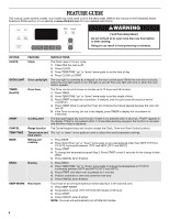
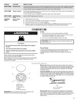
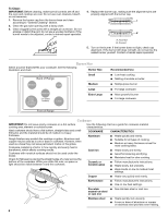
KEYPAD FEATURE START TIME Delayed start COOK TIME Timed cooking SELF CLEAN CONTROL LOCK Self-Cleaning cycle Oven control lockout INSTRUCTIONS The Start Time keypad is used to enter the starting time for an oven function with a delayed start. Start Time should not be used for foods such as breads and cakes because they may not bake properly. To set a Timed Cook or a Delayed Timed Cook, see "Cook Time" section. Timed Cooking allows the oven to be set to turn on at a certain time of day, cook for a set length of time, and/or shut off automatically. To set a Timed Cook or a Delayed Timed Cook, see "Cook Time" section. See the "Self-Cleaning Cycle" section. 1. Check that the oven is off. 2. Press and hold the CONTROL LOCK keypad for 3 seconds. 3. A tone will sound, and "Loc" will be displayed. 4. Repeat to unlock. Only the CLOCK, OVEN LIGHT and TIMER keypads will function with the controls locked. The cooktop functions are not affected by the oven control lockout. WARNING COOKTOP USE To Set: 1. Push in and turn knob counterclockwise to IGNITE. All surface burners will click. Only the burner with the control knob turned to IGNITE will produce a flame. 2. Turn knob to anywhere between HIGH and LOW. Fire Hazard Do not let the burner flame extend beyond the edge of the pan. Turn off all controls when not cooking. Failure to follow these instructions can result in death or fire. Electric igniters automatically light the surface burners when control knobs are turned to IGNITE. Before setting a control knob, place filled cookware on the grate. Do not operate a burner using empty cookware or without cookware on the grate. REMEMBER: When range is in use, the entire cooktop area may become hot. Power Failure In case of prolonged power failure, the surface burners can be lit manually. Hold a lit match near a burner and turn knob counterclockwise to IGNITE. After burner lights, turn knob to setting. Sealed Surface Burners Burner cap: Always keep the burner cap in place when using a surface burner. A clean burner cap will help avoid poor ignition and A uneven flames. Always clean the burner cap after a spillover and routinely remove and clean the caps according to the "General Cleaning" section. Gas tube opening: Gas must flow freely throughout the gas tube opening for the burner to light properly. Keep this area free of soil B D and do not allow spills, food, cleaning agents or any other material to enter the gas tube opening. Keep spillovers out of the gas tube by always using a burner cap. E A C A. Burner cap B. Burner base C. Alignment pins D. Igniter E. Gas tube opening IMPORTANT: Do not obstruct the flow of combustion and ventilation air around the burner grate edges. B A. 1-1¹⁄₂" (25-38 mm) B. Burner ports Burner ports: Check burner flames occasionally for proper size and shape as shown in the previous illustration. A good flame is blue in color, not yellow. Keep this area free of soil and do not allow spills, food, cleaning agents or any other material to enter the burner ports. 5
-
 1
1 -
 2
2 -
 3
3 -
 4
4 -
 5
5 -
 6
6 -
 7
7 -
 8
8 -
 9
9 -
 10
10 -
 11
11 -
12
-
13
-
14
-
15
-
16
 |
 |
