Whirlpool WML75011HN Tech Sheet
Whirlpool WML75011HN Manual
 |
View all Whirlpool WML75011HN manuals
Add to My Manuals
Save this manual to your list of manuals |
Whirlpool WML75011HN manual content summary:
- Whirlpool WML75011HN | Tech Sheet - Page 1
broken. W11279382A FOR SERVICE TECHNICIAN'S USE ONLY FOR SERVICE TECHNICIAN'S USE ONLY FAILURE CODE INDICATIONS NOTE: Many of the problems listed in the NC) (NO) P 2-1 Secondary Interlock Switch NOT HEATING TROUBLESHOOTING INSTRUCTION IMPORTANT: High-voltage is present at the magnetron and - Whirlpool WML75011HN | Tech Sheet - Page 2
60 to 160 ohms (approximate); Blue (BU) and White (WH) wires: 80 to 150 ohms (approximate) 1. If "NTC SHORT, CALL FOR SERVICE" or "NTC OPEN, CALL FOR SERVICE" scrolls on display, unplug microwave oven or disconnect power. 2. Measure hood thermistor: ■■ Normal: 10k ohms +/-5% at 77ºF (25ºC) AC Line - Whirlpool WML75011HN | Tech Sheet - Page 3
remise en marche. Le non-respect de ces instructions peut causer un décès ou un choc électrique. test de service ou d'inspection dans les compartiments de génération de microondes, vérifier le magnétron, le guide d'ondes support de contacteur supérieur, le secondaire est monté sur un autre support - Whirlpool WML75011HN | Tech Sheet - Page 4
et blanc (BL) : 80 à 150 ohms (environ) 1. Si le message "NTC SHORT, CALL FOR SERVICE" (NTC court, faire un appel de service) ou "NTC OPEN, CALL FOR SERVICE" (NTC ouvert, faire un appel de service) défile sur l'écran, débrancher le four à micro-ondes ou couper le courant. 2. Mesurer la thermistance
-
 1
1 -
 2
2 -
 3
3 -
 4
4
 |
 |
FOR SERVICE TECHNICIAN’S USE ONLY
FOR SERVICE TECHNICIAN’S USE ONLY
FOR SERVICE TECHNICIAN’S USE ONLY
3
2
4
FOR SERVICE TECHNICIAN’S USE ONLY
Tech Sheet
Do not discard
W11279382A
FOR SERVICE TECHNICIAN’S USE ONLY
DANGER
Electrical Shock Hazard
Only authorized technicians should
perform diagnostic voltage measurements.
After performing voltage measurements,
disconnect power before servicing.
Failure to follow these instructions can
result in death or electrical shock.
WARNING
Electrical Shock Hazard
Disconnect power before servicing.
Replace all parts and panels before
operating.
Failure to do so can result in death or
electrical shock.
Voltage Measurement Safety Information
When performing live voltage measurements, you must do the following:
°
Verify the controls are in the off position so that the appliance does not start when energized.
°
Allow enough space to perform the voltage measurements without obstructions.
°
Keep other people a safe distance away from the appliance to prevent potential injury.
°
Always use the proper testing equipment.
°
After voltage measurements, always disconnect power before servicing.
PRECAUTIONS TO BE OBSERVED BEFORE
AND DURING SERVICING TO AVOID POSSIBLE
EXPOSURE TO EXCESSIVE MICROWAVE ENERGY
a.
Do not operate or allow the oven to be operated with the door
open.
b.
Make the following safety checks on all ovens to be serviced
before activating the magnetron or other microwave source, and
make repairs as necessary:
1.
Interlock Operation
2.
Proper Door Closing
3.
Seal and Sealing Surfaces (Arcing, Wear and Other Damage)
4.
Damage to or Loosening of Hinges and Latches
5.
Evidence of Dropping or Abuse
c.
Before turning on microwave power for any service test or
inspection within the microwave generating compartments, check
the magnetron, wave guide or transmission line, and cavity for
proper alignment, integrity and connections.
d.
Any defective or misadjusted components in the interlock,
monitor, door seal, and microwave generation and transmission
systems shall be repaired, replaced, or adjusted by procedures
described in this manual before the oven is released to the
owner.
e.
A microwave leakage check to verify compliance with the Federal
Performance Standard (CSA in Canada) should be performed on
each oven prior to release to the owner.
f.
Do not attempt to operate the oven if the door glass is broken.
FAILURE CODE INDICATIONS
NOTE:
Many of the problems listed in the chart below may be solved by power cycling: Unplug microwave oven or disconnect power. After 1 minute,
plug in microwave oven or reconnect power.
Display
Likely Failure
Condition
Recommended Repair Procedure
“Enter
clock”
Power failure
After a power failure, “Enter clock” will be flashing. Press CANCEL to end this indication. The colon (:) will appear when in
Standby mode.
F2E1
Touch panel
failure
1.
Unplug microwave oven or disconnect power.
2.
Replace touch panel.
3.
Replace all parts and panels before operating.
4.
Plug in microwave oven or reconnect power.
5.
If problem persists, refer to “ACU Pin Voltage
Matrix.”
F1E4
MW Relay
1.
Unplug microwave oven or disconnect power.
2.
Check wiring to Relay 4903
3.
Check to see if relay (4903 on ACU) contact
has welded closed.
4.
Replace all parts and panels before operating.
5.
Plug in microwave oven or reconnect power.
6.
If problem persists, refer to “ACU Pin Volatage
Matrix” to check P2-2 (Door), P1-3 (N), and
P1-1(L).
F4E4
Humidity
sensor error
1.
Enter the Diagnostics mode (press CANCEL - CANCEL -
START), and then press COOK to display the humidity sensor
reading. If display does not show The value between “2000 and
9000” continue to Step 2.
2.
Unplug microwave oven or disconnect power.
3.
Connect a new humidity sensor ACU to cable.
4.
Replace all parts and panels before operating.
5.
Plug in microwave oven or reconnect power.
6.
Enter the Diagnostics mode (press CANCEL -
CANCEL - START), then press COOK to see if
failure code reappears.
NOTE:
There may be a delay (approximately
1 minute, 20 seconds) before the F4E4 failure
code is displayed.
7.
If the F4E4 failure code reappears, unplug
microwave oven or disconnect power.
8.
Replace ACU.
9.
Replace all parts and panels before operating.
10.
Plug in microwave oven or reconnect power.
F8E5
Exhaust air
template
detection
failure
1.
Enter the Diagnostics mode (press CANCEL - CANCEL -
START), and then press SETUP or CLOCK to display the
exhaust air temperature sensor reading. Verify the sensor
temperature reading is at room temperature (typically 50ºF
to 90ºF [10ºC to 32ºC]) and verify failure code. If failure code
matches complaint, continue to Step 2.
2.
Unplug microwave oven or disconnect power.
3.
Disconnect sensor from ACU.
4.
Measure sensor resistance between connector pins and confirm
reading is between 9.5 k
Ω
and 10.5 k
Ω
at room temperature. If
measurement is not correct or if a short or open circuit is found,
replace sensor.
5.
Replace all parts and panels before operating.
6.
Plug in microwave oven or reconnect power.
7.
Enter the Diagnostics mode (press CANCEL
- CANCEL - START), and then press SETUP
or CLOCK to display the cavity temperature
sensor reading. Verify the sensor temperature
reading. If it is still not correct, replace ACU.
8.
If failure does not reappear, stop.
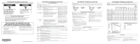
PRIMARY, SECONDARY, MONITOR AND DOOR SWITCH CHECKOUT PROCEDURES
IMPORTANT:
Before checking the interlock switches, unplug microwave oven or disconnect power. Be sure to disconnect all of the wires at the
switch being tested before making any continuity readings.
NOTE:
The Secondary Interlock Switch, Monitor Interlock Switch, Primary Interlock Switch and Door Interlock Switch are mounted in the door lock
switch cradle. All the Interlock Switches can be identified by the wire colors that are connected to the terminals of the switches. See the chart below for
wire color designation.
Switch
Check By
Door Open
Door Closed
Primary
Interlock
1.
Unplug microwave oven or disconnect power.
2.
Disconnect the wires at the Primary Interlock Switch.
3.
Check from the common terminal (black/black wires) to the normally open terminal (black/white wires).
4.
Reconnect wires to switch.
-
+
Monitor
Interlock
1.
Unplug microwave oven or disconnect power.
2.
Disconnect the wires at the Monitor Interlock Switch.
3.
Check from the common terminal (white wire) to the normally closed terminal (blue/blue wires).
4.
Reconnect wires to switch.
+
-
Secondary
Interlock
1.
Unplug microwave oven or disconnect power.
2.
Disconnect the wires at the Secondary Interlock Switch.
3.
Check from the common terminal (white/white wires) to the normally open terminal (blue/black wires).
4.
Reconnect wires to switch.
-
+
Door
Interlock
1.
Unplug microwave oven or disconnect power.
2.
Disconnect the wires at the Door Interlock Switch.
3.
Check from the common terminal (blue wire) to the normally closed terminal (orange wire).
4.
Reconnect wires to switch.
+
-
(+) Continuity (-) No Continuity
NOT HEATING TROUBLESHOOTING INSTRUCTION
IMPORTANT:
High-voltage is present at the magnetron and high-voltage
capacitor terminals. Avoid direct contact when power is connected to
these components to avoid serious injury or possible death. Always be
sure that the high-voltage capacitor is discharged before accessing any
of these components.
For a no-heat condition, refer to the following step-by-step instructions:
1.
Unplug microwave oven or disconnect power.
2.
Discharge the high-voltage capacitor.
3.
Disconnect the high-voltage transformer primary windings.
4.
Attach the voltmeter leads to the high-voltage transformer primary
input wires.
5.
Plug in microwave oven or reconnect power.
6.
Close door and program the microwave oven to operate
for 30 seconds.
7.
Press START.
8.
Check the input voltage at the high-voltage transformer primary
input wires. If the voltage is not close to the rating voltage
120 ± 15 VAC, unplug microwave oven or disconnect power. Check
the circuitry as follows:
■
Measure resistance of the fuse, micro-switches, and thermostats.
Replace any failed components. (Refer to the wiring diagram.)
■
Check for loose terminals. (Refer to the wiring diagram.) Check
all of the terminals on the main route from the power supply to
the high-voltage transformer.
■
Check for loose or failed connectors on the PCBA (P1, P2).
If these check out OK, plug in microwave oven or reconnect
power.
■
Check for ACU failure. Refer to “ACU Pin Voltage Matrix.”
9.
If the input voltage at the high-voltage transformer primary input
wires is close to the rating voltage 120 ± 15 VAC, unplug microwave
oven or disconnect power.
10.
Check the power supply components. Refer to “Component Tests.”
■
High-voltage transformer
■
High-voltage capacitor
■
High-voltage diode
11.
If the power supply components check out OK, check the
connection between the magnetron and the high-voltage
transformer.
12.
If all of the components check out OK, replace the magnetron.
13.
Reconnect the high-voltage transformer primary windings.
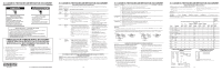
ACU PIN VOLTAGE MATRIX
Check for proper voltage by completing the following steps:
1.
Unplug microwave oven or disconnect power.
2.
Connect voltage measurement equipment to the terminals listed
below. (P1-3 and P2-3 are neutral.)
3.
Plug in microwave oven or reconnect power, and confirm
voltage reading.
4.
Unplug microwave oven or disconnect power.
Abbreviations
HL - Hood Light
N - Neutral
CL - Cavity Light
HF - Hood Fan
L - Line Voltage
TT - Turntable Motor
NFS - Neutral for Switch
NOTE:
When checking voltage readings on ACU, connect the Negative test lead of voltmeter to connector P1-3. Use the positive test lead
to probe connectors designated below.
MW Oven Plugged In—Sitting Idle—ACV Readings
MW Oven
Running—
ACV
Readings
Pin Name
Wire Color
Power
On, Door
Closed
Power On,
Door Open
Hood
Fan
Motor—
High
Hood Fan
Motor—
Med-
High
Hood
Fan
Motor—
Medium
Hood
Fan
Motor—
Low
Hood
Light—
High
Hood
Light—
Low
Microwave
Oven Start
P1-1 (L)
BLACK
120
120
120
N/A
120
120
120
120
120
P1-3 (N)
BLUE
0
0
0
N/A
0
0
0
0
0
P2-1 (NFS)
BLUE AND GREEN
0
0
0
N/A
0
0
0
0
0
P2-2 (Door)
ORANGE
0
120
0
N/A
0
0
0
0
38
P2-3 (N)
WHITE AND BLACK
0
120
0
N/A
0
0
0
0
0
P4-1 (CL/CF)
BLACK
0
120
0
N/A
0
0
0
0
120
P4-2 (TTM)
RED
0
0
0
N/A
0
0
0
0
120
P4-4 (ODM)
BLACK
0
0
0
N/A
0
0
0
0
0
P14-1 (L)
BLACK
120
120
120
N/A
120
120
120
120
120
P14-3 (HF-H)
BLACK
18
20
120
N/A
19
19
19
18
20
P14-4 (HF-L)
WHITE
18
22
20
N/A
19
120
20
19
22
P14-5 (HF-M)
GREY
18
25
19
N/A
120
20
19
18
23
P14-6 (HF-ML)
BLACK
20
23
21
N/A
68
21
21
20
24
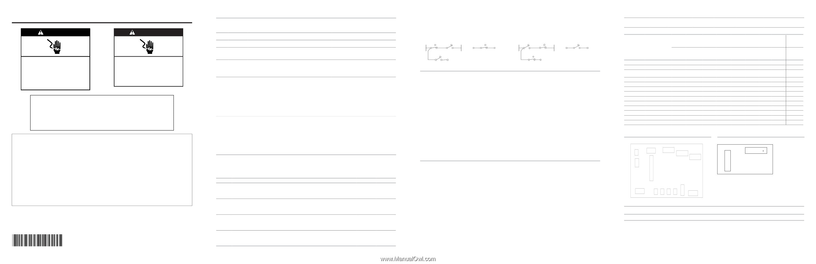
N
(NO)
(NC)
Monitor
Interlock
Switch
Primary
Interlock
Switch
(NC)
(NO)
Secondary
Interlock
Switch
(NC)
(NO)
P 2-3
P 2-1
L
(NO)
(NC)
P 2-2
Door
Interlock
Switch
N
(NO)
(NC)
Monitor
Interlock
Switch
Primary
Interlock
Switch
(NC)
(NO)
Secondary
Interlock
Switch
(NC)
(NO)
P 2-3
P 2-1
L
(NO)
(NC)
P 2-2
Door
Interlock
Switch
Door Closed
Door Open
NOTES:
■
These diagrams are not intended to show a complete circuit; they represent the position of switches during “DOOR OPEN” or “DOOR CLOSED”
(continuity checks only).
■
Interlock and Monitor switches cannot be adjusted and all these switches should be replaced if any one of them is found to be defective. After
replacing interlock/monitor switches, reconnect wires to switch and check for continuity. Safety interlocks and monitor switches will actuate
within 2 mm.
NOTE:
For 50 V and over, the tolerance is ± 15 V. For 0 V, the tolerance is ± 3 V.
NOTE:
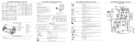
There is a empty terminal on P1 and P4 connector.
TOUCH PANEL
Touch Panel and ACU Test
The microwave hood combination is provided with a self-diagnostic routine that can be accessed through the touch keypad.
To initiate this routine:
1.
Plug in microwave oven or reconnect power, In idle mode, close the
door, turn off hood light and hood fan.
2.
Open and close door, then press CANCEL - CANCEL - START
within 3 seconds.
All LED/LCD segments will be lit to indicate the Test mode has been
entered.
3.
Open door. The model number will be displayed.
4.
Close door. All display segments will be lit.
5.
Press indicated keypad for correct display readout and beep.
NOTE:
If the Cancel button is pressed during this diagnostic routine,
you will exit the Test mode.
2
1
2
1
4
3
6
5
8
7
P9
3
2
1
P8
3
2
1
4
3
2
1
P10
1
2
3
P2
NFS
DOOR
N
2
1
MW-4903
ACU
1
2
.
4
P4
1
.
3
N
P1
L
P5
2
1
P6
3
4
3
2
1
P7
4
3
2
1
P7-1
2
1
2
1
2
1
FC/CL-4904
GRILL ST/HL_LO-490
6
GRILL/HL_HI-4905
CONNECTORS ON PCBA
CONNECTORS ON HOOD CONTROL BOARD
P15
1
1
2
3
3
4
4
5
5
6
6
7
7
8
P14
NOTE:
There is a empty terminal on P14