Whirlpool WML75011HN Tech Sheet - Page 2
For Service Technician's Use Only
 |
View all Whirlpool WML75011HN manuals
Add to My Manuals
Save this manual to your list of manuals |
Page 2 highlights
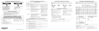
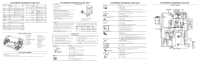
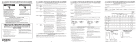
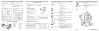
FOR SERVICE TECHNICIAN'S USE ONLY Key Tables for Test Mode Key Name The Upper Function Row Display Buzzer Key Name The Upper Function Row Display Clock Start Start value such as NTC sensor check 1 beep 1 0-200 2 ACU xx.xx.xx ACU SW version check 1 beep 3 UI:xx.xx.xx UI SW version check 1 beep CL Cavity lamp turn on 11 HF_Mid LOW Hood Fan turn on (Mid low Speed) Start LT:xx Left touch SW version 1 beep 4 check HF_Mid_ HIGH Hood Fan turn on (Mid _High Speed) Start Start RT:xx Right touch SW version 1 beep 5 check 6 GEE:xx.xx.xx GEE SW version check 1 beep LCD off HL_HIGH Standby power check Hood Light turn on (high level) ) Hood Light key 03 - Hood Fan key 04 - Timer key 05 - 1 beep 7 1 beep 8 1 beep HL_LOW HF_HIGH Hood Light turn on (low level) Hood Fan turn on (High Speed) Turntable On/ key 09 - Off 1 beep 9 HF_LOW Hood Fan turn on (LOW Speed) Cook value between Humidity sensor check 1 beep 2000 and 9000 Cancel : or xx:xx exit test mode to idle mode Power - - 1 beep Reheat key 24 - 1 beep Defrost key 29 - 1 beep AccuPop key 25 - 1 beep Steam/Simmer key 31 - 1 beep 0 key 10 1 beep Buzzer 1 beep 1 beep 1 beep 1 beep 1 beep 1 beep 1 beep 1 beep 1 beep 1 beep Z AA Y X W V U T S R1 R Q PARTS LAYOUT (NOT TO SCALE) AB AC A B C D E G H K A. Main fuse 20 A B. Motor capacitor C. Cement resistor D. H.V. capacitor E. Magnetron G. Magnetron Thermostat - opens at 257° F (125° C ), closes at 203°F (95°C ) H. Hood motor K. HV transformer L. Open door motor M. Cooling fan motor N. NTC sensor O. ACU L M N O P P. Touch panel Q. Door open switch R. Secondary interlock switch R1. Door interlock switch S. Monitor interlock switch T. Primary interlock switch U. Hood control board V. Turntable motor W Hood (cooktop) light X. Cavity light Y. Hood motor Z. Motor capacitor AA. AC filter AB. Cavity thermostat-opens at 275°F (135°C ), nonresettable AC. Filter board POWER OUTPUT MEASUREMENT The power output of the magnetron can be measured using the following "Voltage Measurement at Power Source" and "Output Test" sections. Before you perform the test: ■■ Make sure that the oven cavity is cool and clean. ■■ Check the line voltage at the wall outlet while microwave oven is operating. See the "Voltage Measurement at Power Source" section. 5 FOR SERVICE TECHNICIAN'S USE ONLY Tools Needed Measure Voltage ■■ 2-cup measuring cup ■■ Thermometer ■■ Voltmeter/ohmmeter Voltage Measurement at Power Source 1. Fill the measuring cup with 2 cups (500 mL) of tap water. 2. Place in the center of the microwave oven cavity. 3. Operate the microwave oven on high power for 1 minute. 4. While the microwave oven is operating, measure the line voltage at the power source. See "Measure Voltage" illustration. 5. Verify the voltage is constant during microwave oven operation. If voltage drops below 108V, contact a qualified electrician to check your electrical supply. 6. Make note of the voltage while the microwave oven is running and proceed to the output test. A B C A. House power supply wall outlet B. Voltmeter/ohmmeter test leads C. Microwave oven plug Output Test 1. Fill the measuring cup with 2 cups (500 mL) of 70ºF (21ºC) tap water. 2. Stir the water with the thermometer to ensure uniform temperature. Add warm or cool water to bring the water to the correct temperature. 3. Place the measuring cup in the center of the microwave oven cavity. 4. Operate the microwave oven on high power for 1 minute. 5. Remove the measuring cup and stir the water with the thermometer for about 20 seconds. 6. Record the temperature of the water. 7. Refer to the model serial tag on the microwave oven to acquire wattage output rating of the microwave oven. 8. Using the following chart, determine if the output of the microwave oven is within the range listed based on the line voltage and wattage rating of the microwave oven. Water Temperature for Line Voltage and Wattage Rating Voltage 700 W 1000 W 1200 W 120 V 96ºF to 102ºF 110ºF to 116ºF 124ºF to 130ºF (36ºC to 39ºC) (43ºC to 47ºC) (51ºC to 54ºC) 108 V 91ºF to 97ºF 101ºF to 107ºF 111ºF to 117ºF (33ºC to 36ºC) (38ºC to 42ºC) (44ºC to 47ºC) COMPONENT TESTS IMPORTANT: ■■ Unplug microwave oven or disconnect power. ■■ Discharge the high-voltage capacitor and remove the lead wires from the primary winding of the high-voltage transformer before conducting any of the following tests. ■■ Conduct a microwave energy test after performing any tests or repairs to the microwave oven. ■■ Check that all wire leads are in the correct positions before operating the microwave oven. ■■ Remove the lead wires from the related component before conducting any of the following tests. ■■ Grasp wire connectors when removing the wire leads from microwave oven parts. ■■ All operational checks using microwave energy must be done with the microwave oven loaded with a minimum of 8 oz (250 mL) of water in a microwave-safe container. ■■ All testing must be done with an ohmmeter having a sensitivity of 20,000 ohms per volt DC or greater and powered by at least a 9 V battery. Components H.V. Transformer Filament (orange/red wires) Primary Secondary (white wire - ground to transformer case) Magnetron Test/Results 1. Unplug microwave oven or disconnect power. 2. Remove wire leads. 3. Measure resistance: ■■ Primary winding: Less than 0.5 ohm (approximate) ■■ Secondary winding: 120 ohms (approximate) ■■ Filament winding: 0 ohms ■■ Primary winding to grounding: Normal: Infinite ■■ Filament winding to grounding: Normal: Infinite 1. Unplug microwave oven or disconnect power. 2. Remove wire leads. 3. Measure resistance: ■■ Filament terminal: Normal: Less than 1 ohm ■■ Filament to chassis: Normal: Infinite 6 FOR SERVICE TECHNICIAN'S USE ONLY P5 3551 Components H.V. Capacitor H.V. Diode Turntable Motor/Open Door Motor Motor Capacitor Humidity Sensor PCBA 1 2 3 4 Hood Exhaust Fan Motor HF NTC Thermistor Test/Results 1. Unplug microwave oven or disconnect power. 2. Remove wire leads. 3. Measure resistance: ■■ Terminal to terminal: Normal: Momentarily indicates several ohms, gradually returns to Infinite ■■ Terminal to case: Normal: Infinite NOTE: Some inexpensive meters may indicate infinite resistance in both directions. 1. Unplug microwave oven or disconnect power. 2. Measure resistance: ■■ Forward: Normal: Continuity ■■ Reverse: Normal: Infinite 1. Unplug microwave oven or disconnect power. 2. Remove wire leads. 3. Measure resistance: ■■ Normal: 2.4k to 3.2k ohms (approximate) 1. Unplug microwave oven or disconnect power. 2. Remove wire leads. 3. Measure resistance: ■■ Normal: Momentarily 0 ohms, then goes to Infinite 1. Unplug microwave oven or disconnect power. 2. Remove the 4-pin connector from the cable. 3. Measure resistance across pins 1 and 2. ■■ Normal: 10K ohms +/-5% at 77°F (25°C) 4. Measure capacity value across pins 3 and 4. ■■ Normal: 180pF +/-5% at 55%RH 1. Unplug microwave oven or disconnect power. 2. Remove wire leads. 3. Measure resistance: ■■ High Speed-Normal: Red (RD) and Blue (BU) wires: 70 to 170 ohms (approximate); Blue (BU) and Black (BK) wires: 20 to 100 ohms (approximate) ■■ Middle Speed-Normal: Grey(GY) and Blue(BU) wires: 50 to 130 (approximate) ■■ Low Speed-Normal: White(WH) and Blue (BU) wires: 60 to 160 ohms (approximate); Blue (BU) and White (WH) wires: 80 to 150 ohms (approximate) 1. If "NTC SHORT, CALL FOR SERVICE" or "NTC OPEN, CALL FOR SERVICE" scrolls on display, unplug microwave oven or disconnect power. 2. Measure hood thermistor: ■■ Normal: 10k ohms +/-5% at 77ºF (25ºC) AC Line Filter Board 1. Unplug microwave oven or disconnect power. 2. Remove wire leads. 3. Measure resistance: ■■ Normal: L-IN to L-OUT (coil): Less than 1 ohm; N-IN to N-OUT (coil): Less than 1 ohm Thermostats Cavity Thermostats Magnetron Thermostat Open Door Switch Switch NOTE: Refer to "Parts Layout" for opening and closing temperatures. 1. Unplug microwave oven or disconnect power. 2. Remove wire leads. 3. Measure continuity: ■■ Normal: Continuity 1. Unplug microwave oven or disconnect power. 2. Remove wire leads. 3. Make sure the switch is pressed 4. Measure resistance: ■■ Normal: >1M ohm ■■ Abnormal:
-
 1
1 -
 2
2 -
 3
3 -
 4
4
 |
 |
