Whirlpool WRT519SZDW W10872127.pdf - Page 1
Whirlpool WRT519SZDW Manual
 |
View all Whirlpool WRT519SZDW manuals
Add to My Manuals
Save this manual to your list of manuals |
Page 1 highlights
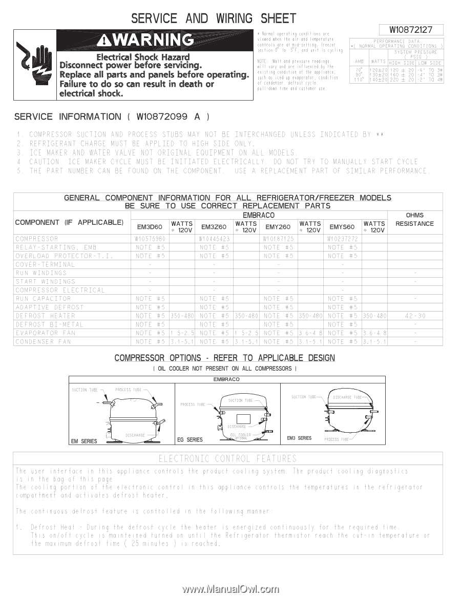
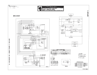
SERVICE AND WIRING ©WARNING Electrical Shock Hazard Disconnect power before servicing. Replace all parts and panels before operating. Failure to do so can result in death or electrical shock. SHEET * Normal operat ing condi t ions are v iewed when the ai r and temperature control s are at mid -sett ing, freezer sect ion 0° to -5° F, and un it is cyc l ing. NOTE: Watt and pressure readi ngs wi l l vary and are infl uenced by the ex ist ing condi t ion of the appl iance, such as iced-up evaporator , condi t ion of condenser, defrost cyc le, pu l l-down t ime and customer use. W10872127 PERFORMANCE DATA *( NORMAL OPERATING CONDITIONS ) SYSTEM PRESSURE ( PSIG ) AMB WATTS HIGH SIDE LOW SIDE 70° 120±20 120 ± 20 -6" TO 3# 90° 130+20 160 ± 20 -4" TO 3# 110° 140±20 220 ± 20 -2" TO 4# SERVICE INFORMATION ( W10872099 A ) 1 . COMPRESSOR SUCTION AND PROCESS STUBS MAY NOT BE INTERCHANGED UNLESS INDICATED BY ** 2 REFRIGERANT CHARGE MUST BE APPLIED TO HIGH SIDE ONLY. 3. ICE MAKER AND WATER VALVE NOT ORIGINAL EQUIPMENT ON ALL MODELS. 4. CAUTION: ICE MAKER CYCLE MUST BE INITIATED ELECTRICALLY. DO NOT TRY TO MANUALLY START CYCLE. 5. THE PART NUMBER CAN BE FOUND ON THE COMPONENT. USE A REPLACEMENT PART OF SIMILAR PERFORMANCE . GENERAL COMPONENT INFORMATION FOR ALL REFRIGERATOR/FREEZER MODELS BE SURE TO USE CORRECT REPLACEMENT PARTS COMPONENT (IF APPLICABLE) EM3D6O WATTS o 12OV EM3Z6O EMBRACO WATTS o 12OV EMY26O WATTS 0 12OV EMYS6O WATTS o 12OV OHMS RESISTANCE COMPRESSOR 810575980 810445423 810187125 810237272 RELAY -STARTING, EMB NOTE #5 NOTE #5 NOTE #5 NOTE #5 OVERLOAD PROTECTOR-T. I. NOTE #5 NOTE #5 NOTE #5 NOTE #5 COVER -TERMINAL RUN WINDINGS START WINDINGS COMPRESSOR ELECTRICAL RUN CAPACITOR NOTE #5 NOTE #5 NOTE #5 NOTE #5 ADAPTIVE DEFROST NOTE #5 NOTE #5 NOTE #5 NOTE #5 DEFROST HEATER NOTE #5 350-480 NOTE #5 350-480 NOTE #5 350-480 NOTE #5 350-480 42-30 DEFROST BI -METAL NOTE #5 NOTE #5 NOTE #5 NOTE #5 EVAPORATOR FAN NOTE #5 1 .5-2.5 NOTE #5 1 .5-2.5 NOTE #5 3.6-4.8 NOTE #5 3.6-4.8 CONDENSER FAN NOTE #5 3. 1-5. 1 NOTE #5 3. 1-5. 1 NOTE #5 3. 1 -5. 1 NOTE #5 3. 1-5. 1 SUCTION TUBE _ COMPRESSOR OPTIONS - REFER TO APPLICABLE DESIGN I OIL COOLER NOT PRESENT ON ALL COMPRESSORS I EMBRACO PROCESS TUBE . PROCESS TUBE SUCTION TUBE SUCTION TUBE DISCHARGE TUBE EM SERIES DISCHARGE EG SERIES DISCHARGE OIL COOLER OPTIONAL EM3 SERIES PROCESS TUBE ELECTRONIC CONTROL FEATURES The user i nterface i n th i s app l iance control s the product cool i ng system. The product coo l i ng d iagnost ics I s I n the bag of th i s page . The cool i ng port ion of the e lectron ic contro l i n th is app l iance control s the temperatures i n the refr igerator compartment and act i vates defrost heater . The cont i nuous defrost feature i s control led i n the fo l lowi ng manner : 1 . Defrost Heat - Dur i ng the defrost cyc le the heater i s energ ized cont i nuous ly for the requ ired t ime. Th i s on/off cyc le I s ma I nte I ned turned on unt I I the Refr igerator thermI stor reach the cut - I n temperature or the max imum defrost t ime ( 25 mi nutes ) i s reached.
-
 1
1 -
 2
2 -
 3
3
 |
 |