Whirlpool WRT519SZDW W10872127.pdf - Page 2
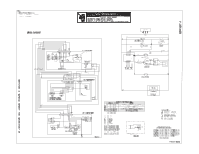
Switch, Diagram
 |
View all Whirlpool WRT519SZDW manuals
Add to My Manuals
Save this manual to your list of manuals |
Page 2 highlights
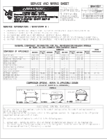
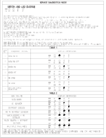
SWITCH AND LED DIAGRAM I I0 0 0 0 SW1 D9 D8 D7 D6 SERVICE DIAGNOSTICS MODE To ENTER SERVICE DIAGNOSTICS Mode: Un i t must be i n the mi n imum temperature sett i ng (D9 on) pr i or to enter i ng SERVICE DIAGNOSTIC MODE . Press SW1 and ho l d door swi tch for 5 seconds . Re l ease the button when a l I LED's are turned on . Al I LED' s turn ON and turn OFF after 10 sec . The d i sp l ay wi l l show D9 on to i nd i cate the contro l i s i n step 1 of the d i agnost i cs rout i ne . Each step must be manua l ly advanced . Press SW1 to move to the next step i n the sequence . Di agnost i cs wi l l beg i n at Step 1 fo l l owi ng the sequence shown i n Tab l e 1 . To guarantee good vo l tage compar i son to i nd i cate l oad fa i l ure, a mi n imum of 2 seconds i s needed i n each step for system stabi l i zat i on . Al I thermi stors wi l l be tested wi thout act i on requ i red from Serv i ce Techn i c i an . Th i s check i s done after Heater Off (Step 4). To EXIT SERVICE DIAGNOSTICS Mode, do one of the fo l l owi ng 3 opt i ons : 1 After l ast step press SW1 2 Di sconnect the product from power . 3 Al l ow 20 mi nutes to pass . Fo l l owi ng the ex i t of the d i agnost i c mode, the contro l s wi l l then resume norma l operat i on . PASS CONDITION: Press i ng SW1 wh i l e i n Step 7 the system returns to normal mode . FAIL CONDITION: Press i ng SW1 wh i l e Step 7 fa i I message status i s d i sp l ay by b l i nk i ng a l I 4 LED's SW1 , the LED's wi l l show for the spec i f i c fai l ure as shown i n Tab l e 2 TABLE 1 Step No. Component Tested DISPLAY INFORMATION Press aga i n 1 COOLING ON II 0 • 0 0 SW1 D9 D8 D7 D6 2 COOLING OFF I1 0 0 0 0 581 D9 D8 37 D6 • 0 0 0 0 0 0 00 I '' 3 HEATER ON ' SW1 D9 D8 D7 D6 4 HEATER OFF 5 NO LOAD 6 NO LOAD I1 0 0 0 0 SW1 D9 D8 D7 D6 11 0 0 0 • SW1 D9 D8 D 7 D6 iI 0 0 0 0 SW1 D9 D8 D 7 D6 SERVICE CHECK COMPLETED ' SW1 D9 D8 D 7 D6 TABLE 2 LOAD FAILURE DISPLAY INFORMATION MAIN BOARD RC SENSOR DEFROST SENSOR RC & DEFROST SENSOR MAIN BOARD + RC SENSOR MAIN BOARD + DEFROST SENSOR MULTIPLE FAILURES '' 0 • 0 0 sw1 D9 D8 D7 D6 '1 0 0 • 0 SW1 D9 D8 D7 D6 0 0 0 • SW1 D9 D8 D7 D6 i swi D9 D8 D7 D6 '' 0 • • 0 SW1 D9 D8 D7 D6 '' 0 • 0 • SW1 D9 D8 D7 D6 i 0 • • • swi D9 D8 D7 D6 NOTE : WHEN MORE THAN ONE FAILURE IS DETECTED, THE MAJOR FAIL IS SHOWED WHEN SERVICE MODE IS ENTERED, ALL MAIN CONTROL BOARD LOADS: DEFROST HEATER, COMPRESSOR, FANS, ETC. ARE TURNED OFF. ONLY THE LOAD BEING CHECKED DURING A DIAGNOSTIC STEP IS ENERGIZED.
-
 1
1 -
 2
2 -
 3
3
 |
 |
