Yamaha 03D Owner's Manual - Page 35
R with Two DA-88s
 |
View all Yamaha 03D manuals
Add to My Manuals
Save this manual to your list of manuals |
Page 35 highlights
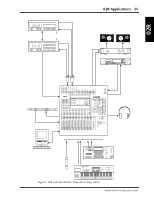
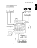
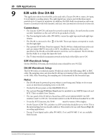
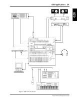
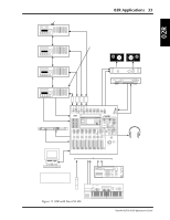
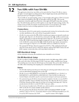
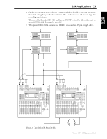
30 02R Applications 10 02R with Two DA-88s This application shows how the 02R can be used with two Tascam DA-88s to create a 24-input, 16-track digital recording system. The 16 tape returns and 24 Mic/Line inputs provide up to 40 inputs at mixdown. In addition, the 02R's built-in automation and scene memory systems provide both dynamic and static mix automation referenced to timecode. Connections • The Tascam (CD8-TD) cards must be screwed securely in place. Do not leave the screws out after installation as the cards will not be grounded correctly. • The Tascam digital audio cables (PW-88DL) carry the eight tape sends and returns. • DA-88-A is connected to Slot [1] of the 02R. These tape inputs correspond to tracks one through eight. DA-88-B is connected to Slot [2] of the 02R. These tape inputs correspond to tracks nine through sixteen. • The optional SY-88 Sync Board is required for DA-88-A. This enables the dedicated timecode track, which can be re-striped at anytime, and provides SMPTE timecode and MTC outputs. A timecode offset can be specified on DA-88-A, so the 02R automix start time can be adjusted. 02R Wordclock Setup On the DIGITAL I/O menu, the wordclock source should be set to W.CLK. DA-88 Wordclock Setup DA-88-A works as wordclock master. Wordclock is fed to the 02R using a BNC to BNC cable, and to the DA-88-B using a PW-88S 15-pin sync cable. The sampling rate is set when the DA-88 tapes are formatted. This can be either 48 kHz or 44.1 kHz. After formatting, the sampling rate is determined by the formatted tape. Notes • The DA-88s must be powered up even when they are not being used. Failure to do so may cause an intermittent pumping noise on the 02R. • DA-88-A is set to MACHINE ID 0. DA-88-B is set to MACHINE ID 1. Since DA-88-A works as Control Master, it should be used for synchronized transport and locate operations. • The optional Tascam SY-88 Sync Board must be installed in DA-88-A to use SMPTE timecode and MTC. This is available from Tascam. DA-88-B does not require the SY-88 Sync Board nor does its tape have to be striped with timecode. It is synchronized to DA-88-A via the PW-88S 15-pin sync cable. • The terminator bundled with the PW-88S sync cable should be connected to the SYNC OUT on DA-88-B to ensure reliable synchronization. • The rear panel of the SY-88 Sync Board has a DIP switch labeled MODE. Set DIP switches 2 and 5 to ON (O). Set internal switch 8 on the SY-88 board marked S2 to ON. • To use the MTC function, the SY-88 firmware must be version 3.08 or higher. • On the Tascam (CD8-TD) card there is a DIP switch that should be set to 16-bit. This is the initial setting, but you should confirm it. This switch is for use with Tascam High-Bit recording applications. • Tascam 25-pin digital audio cables PW-88DL (5 m) and PW-88D (1 m), and the 15-pin PW-88S sync cable are available from Tascam. Yamaha 02R & 03D Applications Guide
-
 1
1 -
2
-
3
-
4
-
5
-
6
-
7
-
8
-
9
-
10
-
11
-
12
-
13
-
14
-
15
-
16
-
17
-
18
-
19
-
20
-
21
-
22
-
23
-
24
-
25
-
26
-
27
-
28
-
29
-
 30
30 -
 31
31 -
 32
32 -
 33
33 -
 34
34 -
 35
35 -
 36
36 -
 37
37 -
 38
38 -
 39
39 -
 40
40 -
41
-
42
-
43
-
44
-
45
-
46
-
47
-
48
-
49
-
50
-
51
-
52
-
53
-
54
-
55
-
56
-
57
-
58
-
59
-
60
-
61
-
62
-
63
-
64
-
65
-
66
-
67
-
68
-
69
-
70
-
71
-
72
-
73
-
74
-
75
-
76
-
77
-
78
-
79
-
80
-
81
-
82
-
83
-
84
-
85
-
86
-
87
-
88
-
89
 |
 |