Yamaha CDX-590 Owner's Manual - Page 4
Connections, Cdx-890
 |
View all Yamaha CDX-590 manuals
Add to My Manuals
Save this manual to your list of manuals |
Page 4 highlights
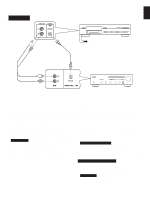
CONNECTIONS • Before making any connections, switch OFF the power to the unit and the amplifier or other component. • Connections should be made to the correct input terminals of the amplifier or other component. • If the placement of this unit causes noise to other equipment, such as a tuner, separate them from each other. CDX-890 LINE OUT VARIABLE FIXED DIGITAL OUT OPTICAL COAXIAL CDX-890 – Connection cord (included) — Optical fiber cable (not included) To AC outlet ˜ Connection cord (not included) CD OPTICAL COAXIAL DIGITAL IN CDX-590 LINE OUT DIGITAL OUT OPTICAL COAXIAL Amplifier CDX-590 – Connection cord (included) — Optical fiber cable (not included) To AC outlet ˜ Connection cord (not included) CD OPTICAL COAXIAL DIGITAL IN Amplifier 4
-
 1
1 -
 2
2 -
 3
3 -
 4
4 -
 5
5 -
 6
6 -
 7
7 -
 8
8 -
 9
9 -
 10
10 -
11
-
12
-
13
-
14
-
15
-
16
-
17
-
18
-
19
-
20
-
21
-
22
-
23
 |
 |
