Yamaha CVP-94 Reference Manual - Page 62
Montieren Sie die Rückwand B.
 |
View all Yamaha CVP-94 manuals
Add to My Manuals
Save this manual to your list of manuals |
Page 62 highlights
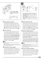
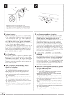
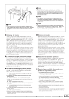
3 • 4 x 12 mm round-head screws 2 4 • 4 x 12 mm Halbrundschrauben 2 • Vis à tête ronde de 4 x 12 mm 2 • Tornillos de cabeza redonda de 4 x 12 mm 2 15 cm A D B • 4 x 20 mm tapping screws 3 • 4 x 20 mm Schneidschrauben 2 • Vis auto-taraudeuses 4 x 20 mm 2 • Tornillos de autoenrosque de 4 x 20 mm 2 L R L R 15 cm D • Be sure to place your hands at least 15 centimeters from either end of the main unit when positioning it. • Mindestens 15 cm innen unter die Tastatureinheit greifen. • Placez bien vos mains à 15 cm au moins des extrémités du clavier, lors de sa mise en place. • Asegúrese de colocar las manos por lo menos a 15 centímetros desde los extremos de la unidad principal cuando la sitúe. CAttach the rear panel (B). With the rear panel slightly angled as shown in the illustration, lower it onto the feet's protruding edge at the rear of the pedal box. Then, while eliminating any gaps between the rear and side panels, secure the top of the rear panel to the side panel brackets using two 4 x 12 mm round-head screws 2. Finally, secure the bottom of the rear panel to the pedal box using four 4 x 20 mm tapping screws 3. VInstall the main unit (A). Place the main unit (A) on the side panels (D) with the screws on its bottom panel (toward the rear of the main unit) just behind the grooves in the brackets located at the top of the side panels. Then slide the main unit forward until it stops. WATCH YOUR FINGERS WHEN DOING THIS!! Align the holes on the bottom panel of the main unit with the holes in the brackets on the side panels (also center the main unit to produce equal clearance on the left and right sides, as shown in the illustration), then screw in and securely tighten the four 6 x 16 millimeter flat-head screws 4. • Do not hold the keyboard in any position other than the position shown in the above illustration. • Fingers can become pinched between the main unit and the rear or side panels, be extra careful so as not to drop the main unit. BConnect the pedal cord. The pedal cord from the pedal box must be plugged into the corresponding connector in the main unit. The plug only goes in one way (the lug on the connector should face the rear of the main unit, as shown in the illustration), so don't try to force it in the wrong way around. Once connected, attach the cord holders to the rear panel as shown, then clip the cord into the holders. 40 CMontieren Sie die Rückwand (B). Setzen Sie die Rückwand leicht abgewinkelt, wie in der Abbildung gezeigt, hinter dem Pedalkasten auf die hervorspringenden Teile der Füße auf. Schrauben Sie dann die Rückwand oben mit zwei 4 x 12 mm Halbrundschrauben 2 so an den Seitenwänden fest, daß kein Spiel zwischen Rückwand und Seitenwänden verbleibt. Schrauben Sie die Rückwand abschließend noch mit vier 4 x 20 mm Schneidschrauben 3 an den Pedalkasten. VMontieren Sie die Tastatureinheit (A). Setzen Sie die Tastatureinheit (A) so auf den fertigen Ständer, daß die beiden Schrauben an ihrer Unterseite hinter den Winkelblechen mit Führungsschlitz an der Hinterseite des Ständers zu liegen kommen. Schieben Sie die Tastatureinheit dann bis zum Anschlag in die Schlitze. KLEMMEN SIE IHRE FINGER DABEI NICHT EIN!! Richten Sie die Schraubenbohrungen an der Unterseite der Tastatureinheit mit den Bohrungen der Winkelbleche aus (achten Sie auch darauf, daß sie mittig auf dem Ständer steht, wie in der Abbildung gezeigt). Schrauben Sie die Tastatureinheit dann mit den vier 6 x 16 mm Senkschrauben 4 am Ständer fest. • Halten Sie die Tastatureinheit nur wie in der obigen Abbildung! • Achten Sie darauf, daß Sie Ihre Finger nicht zwischen Tastatur- einheit und den Seitenwänden bzw. der Rückwand einklemmen - die Tastatureinheit könnte dadurch zu Fall kommen! BSchließen Sie das Pedalkabel an. Das vom Pedalkasten kommende Kabel wird an die entsprechende Buchse der Tastatureinheit angeschlossen. Der Kabelstecker paßt nur in einer Ausrichtung in die Buchse (mit der Führungsnase zur Rückseite des Instruments weisend, wie in der Abbildung verdeutlicht). Versuchen Sie nicht, den Stecker falsch herum mit Gewalt in die Buchse zu drücken! Bringen Sie nach dem Anschluß die Kabelhalter wie in der Abbildung an der Rückwand an, um das Kabel dann in diese Halter zu legen.
-
 1
1 -
2
-
3
-
4
-
5
-
6
-
7
-
8
-
9
-
10
-
11
-
12
-
13
-
14
-
15
-
16
-
17
-
18
-
19
-
20
-
21
-
22
-
23
-
24
-
25
-
26
-
27
-
28
-
29
-
30
-
31
-
32
-
33
-
34
-
35
-
36
-
37
-
38
-
39
-
40
-
41
-
42
-
43
-
44
-
45
-
46
-
47
-
48
-
49
-
50
-
51
-
52
-
53
-
54
-
55
-
56
-
 57
57 -
 58
58 -
 59
59 -
 60
60 -
 61
61 -
 62
62 -
 63
63 -
 64
64 -
 65
65 -
 66
66 -
 67
67 -
68
 |
 |
