Yamaha IMX644 Imx644 Manager Owner's Manual - Page 25
OUTPUT screen
 |
View all Yamaha IMX644 manuals
Add to My Manuals
Save this manual to your list of manuals |
Page 25 highlights
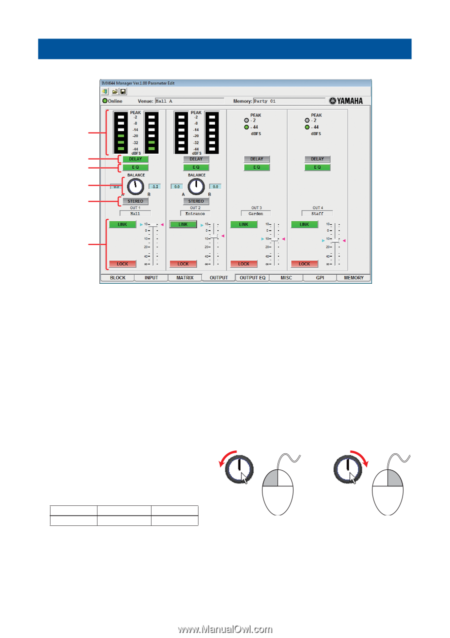
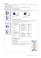
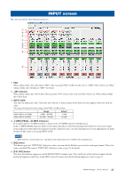
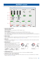
OUTPUT screen Here you can edit parameters other than EQ for output channels 1-4. 1 2 3 4 5 6 1 Output level meter/indicator Output level meters Shows level meters for the output signals of OUTPUT channels 1 and 2. Output indicators Shows [-2 dBFS]/[-44 dBFS] indicators for the output signals of OUTPUT channels 3 and 4. The [-44 dBFS] indicator will light green when an output signal is detected at the corresponding channel. If the [-2 dBFS] (PEAK) indicator lights red, the output signal has reached the maximum allowable level. Lower the input volume or the output volume. 2 [DELAY] button Opens the "DELAY" dialog box, allowing you to specify the delay time for each OUTPUT channel. These parameters are the same as in the BLOCK screen's "DELAY" dialog box; refer to page 21 for details. 3 [EQ] button This button opens the OUTPUT EQ screen (page 26), allowing you to edit the parameters of the 6-band equalizers provided for OUTPUT channels 1 through 4. 4 [BALANCE] knob This knob adjusts the volume balance between outputs A/B (L/R) for OUTPUT channels 1 and 2. Right-click the [BALANCE] knob and continue holding down the mouse button to decrease the A (L) volume; left-click and hold down the mouse button to decrease the B (R) volume. Double-click to reset the value to center. Parameter Range Default Press (hold) the left button Balance 0dB - -20.1dB 0dB Press (hold) the right button 5 [STEREO/MONO] button This button specifies the mode of the output channel. Click it to switch between STEREO and MONO. 6 [LINK] button, fader, marker, [LOCK] button Here you can adjust the volume of the output channel. These parameters are the same as in the BLOCK screen's "LEVEL" dialog box; refer to page 21 for details. IMX644 Manager Owner's Manual 25
-
 1
1 -
2
-
3
-
4
-
5
-
6
-
7
-
8
-
9
-
10
-
11
-
12
-
13
-
14
-
15
-
16
-
17
-
18
-
19
-
 20
20 -
 21
21 -
 22
22 -
 23
23 -
 24
24 -
 25
25 -
 26
26 -
 27
27 -
 28
28 -
 29
29 -
 30
30 -
31
-
32
-
33
-
34
-
35
 |
 |