Yamaha M3000A Owner's Manual - Page 24
Matrix Am1-m16 Bstereo A L/r Csub In L/r Don Elevel Fafl
 |
View all Yamaha M3000A manuals
Add to My Manuals
Save this manual to your list of manuals |
Page 24 highlights
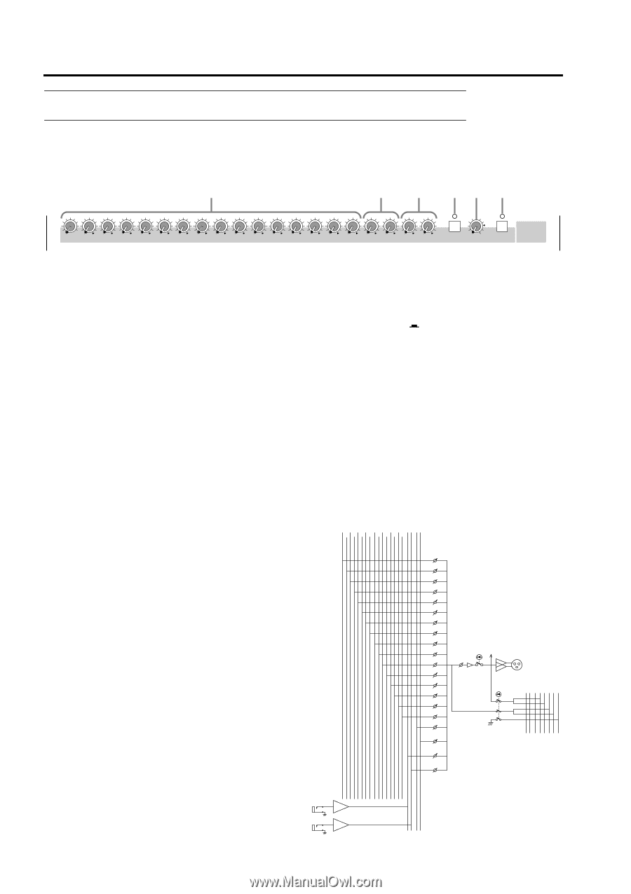
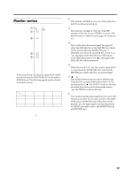
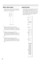
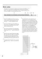
Control panel Matrix section The M3000A provides eight matrices which allow output signals from the MIX buses 1-16 or the ST bus, or input signals from MATRIX SUB IN to be mixed at the desired level. Matrix 1-8 are output in mono from MATRIX OUT jacks 1-8 respectively (page 27), and can be used as foldback or for an individual monitor system. 1 B C DE F 0 M1 0 M2 0 M3 0 M4 0 M5 0 M6 0 M7 0 M8 0 M9 0 M10 0 M11 0 M12 0 M13 0 M14 0 M15 0 M16 0L 0R STEREO A 0L 0R SUB IN ON 0 10 LEVEL AFL MATRIX 1 A M1-M16 controls When the TO MATRIX switch of the mix section is on, these controls adjust the level of the signal which is input from the corresponding MIX OUT to the matrix. The "v" position is nominal level (0 dB). B STEREO A L/R controls When the TO MATRIX switch of the STEREO A section is on, these controls adjust the level of the signal which is input to the matrix from ST OUT A. The "v" position is nominal level (0 dB). C SUB IN L/R controls These controls adjust the level of the signal which is input to the matrix from the rear panel MATRIX SUB IN jacks (page 27). The "v" position is nominal level (0 dB). D ON switch When this switch is turned off, the indicator will go dark, and no signal will be output from the MATRIX OUT jacks. However even in this case, the signal sourced before passing through the LEVEL control can be monitored from the MONITOR OUT jacks or the PHONES jack by turning on the AFL switch (6). E LEVEL control This adjusts the final output level of the corresponding matrix 1-8. The "v" position is nominal level (0 dB). F AFL switch This switch allows the output signal of the corresponding matrix 1-8 to be monitored from the MONITOR OUT jacks or the PHONES jack. When this switch is on ( ), the indicator will light, and the signal before passing through the level control will be sent to the MAS PFL bus, and the signal after passing through the LEVEL control will be sent to the MAS AFL bus, allowing you to monitor them from the MONITOR OUT jacks or the PHONES jack. When the monitor section MASTER PFL switch (page 19) is off, you can monitor the signal of the MAS AFL bus. When the MASTER PFL switch is on, you can monitor the signal of the MAS PFL bus. However if even one of the input channel PFL switches is on, the PFL bus will be given priority for monitoring, meaning that it will not be possible to monitor the matrix. TO MATRIX (MIX) (SUB)(ST) 1 3 5 7 9 11 13 15 L R L R 2 4 6 8 10 12 14 16 M1 M2 M3 M4 M5 M6 M7 M8 M9 M10 M11 M12 M13 M14 M15 M16 STEREO A L STEREO A R SUB IN L SUB IN R LEVEL to Meter ON AFL MATRIX OUT 1-8 MAS MAS PFL AFL PFLAFL L R ON L R L R ON 24 BA L MATRIX SUB IN BA R
-
 1
1 -
2
-
3
-
4
-
5
-
6
-
7
-
8
-
9
-
10
-
11
-
12
-
13
-
14
-
15
-
16
-
17
-
18
-
 19
19 -
 20
20 -
 21
21 -
 22
22 -
 23
23 -
 24
24 -
 25
25 -
 26
26 -
 27
27 -
 28
28 -
 29
29 -
30
-
31
-
32
-
33
-
34
-
35
-
36
-
37
-
38
-
39
-
40
-
41
-
42
-
43
-
44
-
45
-
46
-
47
 |
 |