Yamaha MG12 Owner's Manual - Page 19
Master Control ST Master Fader, GROUP 1-2 Fader, TO ST Switch, Master SEND, RETURN - 4 power supply
 |
View all Yamaha MG12 manuals
Add to My Manuals
Save this manual to your list of manuals |
Page 19 highlights
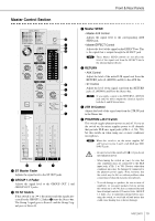
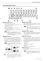
Front & Rear Panels Master Control Section B 7 6 A 0 5 4 9 8 3 C 2 1 1 ST Master Fader Adjusts the signal level to the ST OUT jacks. 2 GROUP 1-2 Fader Adjusts the signal level to the GROUP OUT 1 and GROUP OUT 2 jacks. 3 TO ST Switch If this switch is on ( ), the mixer sends the signals processed by the GROUP 1-2 fader (2) onto the Stereo bus. The Group 1 signal goes to Stereo L and the Group 2 signal goes to Stereo R. 4 Master SEND • Master AUX Control Adjusts the signal level to the corresponding AUX SEND jack. • Master EFFECT Control Adjusts the level of the signal on the EFFECT bus. This is the signal that is output through the EFFECT jack. NOTE These Master SEND controls do not affect the level of the signal sent from the EFFECT bus to the internal digital effector. 5 RETURN • AUX Control Adjust the level of the mixed L/R signal sent from the RETURN jacks (L (MONO) and R) to the AUX bus. • ST Control Adjust the level of the signal sent from the RETURN jacks (L (MONO) and R) to the Stereo bus. NOTE If you supply a signal to the RETURN L (MONO) jack only, the mixer outputs the identical signal to both the L and R Stereo buses. 6 2TR IN Control Adjusts the level of the signal sent from the 2TR IN jack to the Stereo bus. 7 PHANTOM +48 V Switch This switch toggles phantom power on and off. If you set the switch on, the mixer supplies power to all channels that provide XLR mic input jacks (CHs 1-4, 5/6, 7/8). Set this switch on when using one or more condenser microphones. NOTE When this switch is on, the mixer supplies DC +48 V power to pins 2 and 3 of all XLR-type MIC INPUT jacks. • Be sure to leave this switch off ( ) if you do not need phantom power. • When tuning the switch on ( ), be sure that only condenser mics are connected to the XLR input jacks (CHs: 1 to 7/8). Devices other than condenser mics may be damaged if connected to the phantom power supply. Note, however, that the switch may be left on without problem when connecting to balanced dynamic microphones. • To avoid damage to speakers, be sure to turn off amplifiers (or powered speakers) before turning this switch on or off. We also recommend that you turn all output controls (ST master fader, GROUP 1-2 fader, etc.) to minimum settings before operating the switch, to avoid risk of loud noises that could cause hearing loss or device damage. MG12/4FX 19
-
 1
1 -
2
-
3
-
4
-
5
-
6
-
7
-
8
-
9
-
10
-
11
-
12
-
13
-
 14
14 -
 15
15 -
 16
16 -
 17
17 -
 18
18 -
 19
19 -
 20
20 -
 21
21 -
 22
22 -
 23
23 -
 24
24 -
25
-
26
-
27
-
28
-
29
-
30
-
31
-
32
 |
 |
