Yamaha MG12 Owner's Manual - Page 27
Input Speci, cations, Conformed Environment: E1, E2, E3 and E4 - manual
 |
View all Yamaha MG12 manuals
Add to My Manuals
Save this manual to your list of manuals |
Page 27 highlights
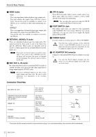
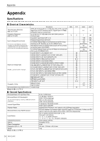
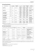
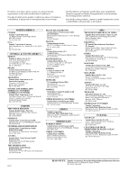
Appendix ■ Input Specifications Input Connector MIC INPUT (CHs 1 to 4) LINE INPUT (CHs 1 to 4) ST CH MIC INPUT (CH5(L)/CH6(R), CH7(L)/CH8(R)) ST CH LINE INPUT (CH5(L)/CH6(R), CH7(L)/CH8(R)) ST CH INPUT (CH9(L)/CH10(R), CH11(L)/CH12(R)) Gain Input Impedance Appropriate Impedance -60 3 kΩ -16 50-600 Ω mic -34 10 kΩ +10 600 Ω line -60 3 kΩ -16 50-600 Ω mic -34 10 kΩ +10 600 Ω line 10 kΩ 600 Ω line Sensitivity* -80 dBu (0.078 mV) -36 dBu (12.3 mV) -54 dBu (1.55 mV) -10 dBu (245 mV) -80 dBu (0.078 mV) -36 dBu (12.3 mV) -54 dBu (1.55 mV) -10 dBu (245 mV) -30 dBu (24.5 mV) Nominal Level -60 dBu (0.775 mV) -16 dBu (123 mV) -34 dBu (15.5 mV) +10 dBu (2.45 V) -60 dBu (0.775 mV) -16 dBu (123 mV) -34 dBu (15.5 mV) +10 dBu (2.45 V) Max. Before Clipping -40 dBu (7.75 mV) +4 dBu (1.23 V) -14 dBu (155 mV) +30 dBu (24.5 V) -40 dBu (7.75 mV) -10 dBu (245 mV) -14 dBu (155 mV) +30 dBu (24.5 V) -10 dBu (245 mV) +10 dBu (2.45 V) CH INSERT IN (CHs 1 to 4) 10 kΩ 600 Ω line -20 dBu (77.5 mV) 0 dBu (0.775 V) +20 dBu (7.75 V) RETURN (L, R) 2TR IN (L, R) Where 0 dBu = 0.775 V and 0 dBV= 1 V 10 kΩ 10 kΩ 600 Ω line 600 Ω line -12 dBu (195 mV) -26 dBV (50.1 mV) +4 dBu (1.23 V) -10 dBV (316 mV) +24 dBu (12.3 V) +10 dBV (3.16 V) * Input sensitivity: the lowest level that will produce the nominal output level when the unit is set to maximum gain. Connector Specifications XLR-3-31 type (balanced) Phone jack (TRS) (balanced [T: hot; R: cold; S: ground]) XLR-3-31 type (balanced) Phone jack (unbalanced) Phone jack (unbalanced); RCA pin jack Phone jack (TRS) (unbalanced [T: out; R: in; S: ground]) Phone jack (unbalanced) RCA pin jack ■ Output Specifications Output Connectors Output Impedance Appropriate Impedance Nominal Level Max. Before Clipping Connector Specifications ST OUT (L, R) 150 Ω 600 Ω line +4 dBu (1.23 V) +24 dBu (12.3 V) XLR-3-32 type (balanced) Phone jack (TRS) (balanced [T: hot; R: cold; S: ground]) GROUP OUT (1-2) AUX SEND EFFECT SEND 150 Ω 10 kΩ line +4 dBu (1.23 V) +20 dBu (7.75 V) Phone jack (TRS) (impedance balanced [T: hot; R: cold; S: ground]) CH INSERT OUT (CHs 1 to 4) 150 Ω 10 kΩ line 0 dBu (0.775 V) +20 dBu (7.75 V) Phone jack (TRS) (unbalanced [T: out; R: in; S: ground]) REC OUT (L, R) 600 Ω 10 kΩ line -10 dBV (316 mV) +10 dBV (3.16 V) RCA pin jack C-R OUT (L, R) 150 Ω 10 kΩ line +4 dBu (1.23 V) +20 dBu (7.75 V) Phone jack (TRS) (impedance balanced [T: hot; R: cold; S: ground]) PHONES 100 Ω 40 Ω phone 3 mW 75 mW Stereo phone jack Where 0 dBu = 0.775 V and 0 dBV= 1 V Specifications and descriptions in this owner's manual are for information purposes only. Yamaha Corp. reserves the right to change or modify products or specifications at any time without prior notice. Since specifications, equipment or options may not be the same in every locale, please check with your Yamaha dealer. For European Model Purchaser/User Information specified in EN55103-1 and EN55103-2. Inrush Current: 3A Conformed Environment: E1, E2, E3 and E4 MG12/4FX 27
-
 1
1 -
2
-
3
-
4
-
5
-
6
-
7
-
8
-
9
-
10
-
11
-
12
-
13
-
14
-
15
-
16
-
17
-
18
-
19
-
20
-
21
-
 22
22 -
 23
23 -
 24
24 -
 25
25 -
 26
26 -
 27
27 -
 28
28 -
 29
29 -
 30
30 -
 31
31 -
 32
32
 |
 |
