Yamaha RSW300 Owners Manual - Page 8
Controls And Their Functions - speakers subwoofers yst
 |
UPC - 027108928173
View all Yamaha RSW300 manuals
Add to My Manuals
Save this manual to your list of manuals |
Page 8 highlights
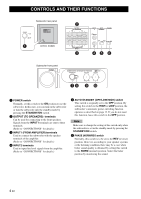
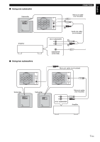
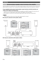
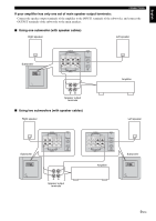
CONTROLS AND THEIR FUNCTIONS 1 Subwoofer rear panel OUTPUT TO SPEAKERS INPUT 1 FROM AMPLIFIER INPUT 2 AUTO STANDBY PHASE /MONO OFF HIGH LOW NORM REV POWER ON OFF (U.S.A. model) 2 OUTPUT TO SPEAKERS R L R L FROM AMPLIFIER INPUT 1 3 INPUT AUTO PHASE 2 STANDBY L /MONO OFF LOWHIGH NORM REV R 45 6 Subwoofer front panel SUBWOOFER SYSTEM YST-RSW300 STANDBY/ON HIGH CUT VOLUME 78 40Hz 140Hz 9 0 10 0 1 POWER switch Normally, set this switch to the ON position to use the subwoofer. In this state, you can turn on the subwoofer or turn the subwoofer into the standby mode by pressing the STANDBY/ON switch. 2 OUTPUT (TO SPEAKERS) terminals Can be used for connecting to the front speakers. Signals from the INPUT1 terminals are sent to these terminals. (Refer to "CONNECTIONS" for details.) 3 INPUT1 (FROM AMPLIFIER) terminals Used to connect the subwoofer with the speaker terminals of the amplifier. (Refer to "CONNECTIONS" for details.) 4 INPUT2 terminals Used to input line level signals from the amplifier. (Refer to "CONNECTIONS" for details.) 5 AUTO STANDBY (OFF/LOW/HIGH) switch This switch is originally set to the OFF position. By setting this switch to the HIGH or LOW position, the subwoofer's automatic power-switching function operates as described on page 13. If you do not need this function, leave this switch in the OFF position. Note Make sure to change the setting of this switch only when the subwoofer is set in the standby mode by pressing the STANDBY/ON switch. 6 PHASE (NORM/REV) switch Normally, this switch is to be set to the REV (reverse) position. However, according to your speaker systems or the listening condition, there may be a case when better sound quality is obtained by setting this switch to the NORM (normal) position. Select the better position by monitoring the sound. 4 En
-
 1
1 -
2
-
 3
3 -
 4
4 -
 5
5 -
 6
6 -
 7
7 -
 8
8 -
 9
9 -
 10
10 -
 11
11 -
 12
12 -
 13
13 -
14
-
15
-
16
-
17
-
18
-
19
-
20
-
21
-
22
-
23
-
24
 |
 |
