Yamaha RX-396 Owner's Manual - Page 8
For Custom Installer, IMPEDANCE SELECTOR switch
 |
View all Yamaha RX-396 manuals
Add to My Manuals
Save this manual to your list of manuals |
Page 8 highlights
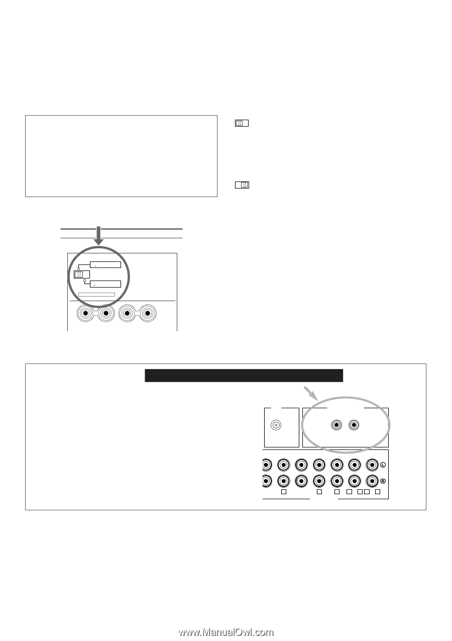
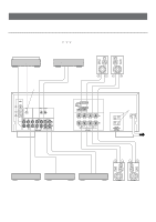
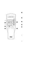
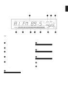
IMPEDANCE SELECTOR switch Be sure to switch the position only when the power to this unit is not on. Select the position whose requirements your speaker system meets. WARNING Do not change the IMPEDANCE SELECTOR switch setting while the power to this unit is on, otherwise this unit may be damaged. IF THIS UNIT FAILS TO TURN ON WHEN THE STANDBY/ON SWITCH IS PRESSED; The IMPEDANCE SELECTOR switch may not be set to either end. If so, set the switch to either end when this unit is in the standby mode. IMPEDANCE SELECTOR (U.S.A. model) A OR B:4ΩMIN. /SPEAKER A B:8ΩMIN. /SPEAKER A OR B: 6ΩMIN. /SPEAKER A B: I2ΩMIN. /SPEAKER IMPEDANCE SELECTOR SET BEFORE POWER ON A (Left position) If you use one pair of speakers, the impedance of each speaker must be 4Ω or higher. If you use two pairs of speakers, the impedance of each speaker must be 8Ω or higher. (Right position) If you use one pair of speakers, the impedance of each speaker must be 6Ω or higher. If you use two pairs of speakers, the impedance of each speaker must be 12Ω or higher. The impedance of each speaker must be 6Ω or higher. If you use one pair of speakers, the impedance of each speaker must be 8Ω or higher. If you use two pairs of speakers, the impedance of each speaker must be 16Ω or higher. For Custom Installer For U.S.A., Canada and Australia models only REMOTE CONTROL (IN, OUT) terminals These terminals are used for custom installation system. When this unit is connected to the components for custom installation system, you can operate this unit with the system remote control. Connect the REMOTE CONTROL IN terminal of this unit to the output terminal of the central controller for custom installation system. By connecting the REMOTE CONTROL OUT terminal of this unit to the REMOTE CONTROL IN terminal of the other component, you can also operate the component with the system remote control. In this way, up to 6 components can be connected in series. GND REMOTE CONTROL IN OUT PHONO CD AUX TAPE 1 PLAY /MD REC TAPE 2 PLAY REC 1 3 4 3 or 5 4 or 6 AUDIO SIGNAL 8
-
 1
1 -
2
-
 3
3 -
 4
4 -
 5
5 -
 6
6 -
 7
7 -
 8
8 -
 9
9 -
 10
10 -
 11
11 -
 12
12 -
 13
13 -
14
-
15
-
16
-
17
-
18
-
19
-
20
-
21
-
22
-
23
-
24
-
25
-
26
-
27
-
28
-
29
 |
 |