Yamaha V1.6 PX10/PX8/PX5/PX3 V1.6 Reference Manual [English] - Page 9
Rear panel, Controls and functions, INPUT] A/B connectors, SPEAKERS] A/B terminals, AC IN] connector
 |
View all Yamaha V1.6 manuals
Add to My Manuals
Save this manual to your list of manuals |
Page 9 highlights
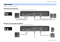
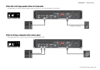
Rear panel !9 Controls and functions - Rear panel !6 !7 !8 !6 [INPUT] A/B connectors Two types of input connectors are provided for both channels A and B. In Single mode or Parallel mode, the input connectors of channel A are used. • XLR jack XLR type 3-31 jack. The polarity is shown below (IEC60268). Hot Ground 21 3 Cold • Phone jack Balanced TRS phone jack. The polarity of the connections is shown below. Ring (cold) Sleeve (ground) Tip (hot) NOTE The XLR input jack and the phones input jack of each channel are connected in parallel. The signal input from an XLR jack can be output from the phone jack and input to another amplifier. Only one of the jacks can be used as an input jack at one time; the signals from the jacks cannot be mixed. !7 [SPEAKERS] A/B terminals Output terminals for speakers. Three types are available (below). • Neutrik NL4MD speakON connector • Binding post connector • Phone jack NOTICE • Do not touch the terminals or metal parts of cords connected to the terminal. If connecting speakers to multiple connectors of the same channel results in a parallel connection, make sure that the total impedance of the speakers to be connected is not excessively low. • The PX amplifier adopts BTL (Balanced Transformer Less) amplifier circuits. Connecting both terminals of channel A and channel B and contact between the terminal and the chassis may cause a failure or malfunction. Be careful not to connect or contact the two by mistake. NOTE In Power Boost mode, the output terminals of channel A are used (PX5/PX3 only). !8 [AC IN] connector Connect the supplied AC power cord. First connect the AC power cord to the connector on the amplifier, and then plug it into an appropriate AC power outlet. Secure the AC power cord with the AC plug clamp to prevent accidental disconnection from the connector. Installing the AC plug clamp q w e !9 Exhaust ports Exhaust vents for the cooling fan. Make sure to not block these ports. PX10/PX8/PX5/PX3 Reference Manual 9
-
 1
1 -
2
-
3
-
 4
4 -
 5
5 -
 6
6 -
 7
7 -
 8
8 -
 9
9 -
 10
10 -
 11
11 -
 12
12 -
 13
13 -
 14
14 -
15
-
16
-
17
-
18
-
19
-
20
-
21
-
22
-
23
-
24
-
25
-
26
-
27
-
28
-
29
-
30
-
31
-
32
-
33
-
34
-
35
-
36
-
37
-
38
-
39
-
40
-
41
-
42
-
43
-
44
-
45
-
46
-
47
-
48
-
49
-
50
-
51
-
52
-
53
-
54
-
55
-
56
 |
 |
