Yamaha YTS-T500 Installation Manual
Yamaha YTS-T500 Manual
 |
View all Yamaha YTS-T500 manuals
Add to My Manuals
Save this manual to your list of manuals |
Yamaha YTS-T500 manual content summary:
- Yamaha YTS-T500 | Installation Manual - Page 1
English Integrated TV/Soundbar Pedestal Socle intégré pour téléviseur et projecteur de son YTS-T500 Printed in Malaysia WU17410-1 G Install Manual Manuel d'installation Installationsanleitung Installationsanvisningar Manuale d'installazione Manual de instalación Installatiehandleiding Franç - Yamaha YTS-T500 | Installation Manual - Page 2
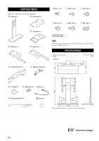
1 : Speaker bracket A × 1 : TV bracket × 1 : Bracket R × 1 Spare: Each size × 1 (6 screws in total) Note In the following assembly procedure, these supplied parts are described as for parts and for screws, etc. SPECIFICATIONS • Dimensions (W × H × D 650 × 867 × 398 mm • Weight ...17.0 kg Unit: mm - Yamaha YTS-T500 | Installation Manual - Page 3
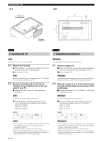
them in order of opposing corner. 1 Assembling the pedestal 1-1 Attach 1-2 Attach to with (7 screws). with (3 screws). Français Avant le montage • Le symbole y appelle votre attention sur un conseil d'utilisation. • Lors du montage, notez les dimensions mesurées et le numéro (qui figure sur - Yamaha YTS-T500 | Installation Manual - Page 4
/MONTAGE 2-1 Blanket, etc. Couverture, etc. 2-2 X Y TV stand Support TV English 2 Installing the TV Français 2 Installation du téléviseur Note Also refer to the owner's manual of your TV. 2-1 Remove the TV stand. 1 Place a blanket, etc. on a flat area, and place the TV on it so that the - Yamaha YTS-T500 | Installation Manual - Page 5
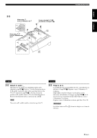
in the illustration above. If and touch each other when you place them on the TV (if X checked in step 2-2-1 is 20 cm), reverse the position of and and secure and . Note The arrows on and should be toward the top of the TV. Français 2-3 Fixez et . Le nombre de trous que possèdent et varie selon - Yamaha YTS-T500 | Installation Manual - Page 6
l'utilisation de YSP-4100 English Français 2-4 Check the location to attach and the TV. 1 Place over mounting hole A on or so that the hole on aligns with in the illustration. 2 Check which number on is at the bottom of your TV. Refer to the number shown on the bar that corresponds to the name - Yamaha YTS-T500 | Installation Manual - Page 7
2-6 Prepare to attach . Place temporarily over and , and check which hole to use. Note The arrow on should be toward the top of the TV. If you use mounting hole B in step 2-5, the mounting holes to attach are shown below. 2-5 Serrez provisoirement (2 vis) pour fixer le téléviseur à . Si vous - Yamaha YTS-T500 | Installation Manual - Page 8
. Before mounting the TV to the pedestal, complete the cable connections. For details, refer to the owner's manual of your TV. Note Also connect the cable for the speaker to the TV. For the details, refer to the owner's manual of your speaker. 2-9 Mount your TV. 1 Hang the TV by inserting the - Yamaha YTS-T500 | Installation Manual - Page 9
to the pedestal, complete the cable connections. For details, refer to the owner's manual of your speaker. • Remove the speaker stand when it Pour plus de détails, consultez le mode d'emploi du haut-parleur. • Retirez le support du haut-parleur si celui-ci est fixé. 3-1 Fixez ou avec (4 vis). - Yamaha YTS-T500 | Installation Manual - Page 10
choice on the right and left of . 2 Bundle the cables with . 3 Move the pedestal holding both the TV and the pedestal. Note Do not hold the speaker, as it may be damaged. y When you position the pedestal against a wall, you can prevent toppling over by the procedure below. Attach . Remove . Secure - Yamaha YTS-T500 | Installation Manual - Page 11
sorgfältig durch. Yamaha ist nicht verantwortlich × 30 40 × 40 50 × 20 60 × 40 * Konform mit dem VESA-Montageschnittstellen-Standard und mit dem Abstand der oben beschriebenen Montagebohrungen. Der Durchmesser der der Lautsprecher-Modellen kompatibel. (Stand: Oktober 2009) YSP-4000, YSP-5100/4100, - Yamaha YTS-T500 | Installation Manual - Page 12
. : Ständer × 1 : Sockel × 1 (M5 × 16) × 7 (M5 × 16) × 7 (M5 × 20) × 8 (M6 × 16) × 8 (M6 × 20) × 4 (M8 × 20) × 4 : Halter L × 1 : TV-Halter × 1 : Halter R × 1 Ersatzschrauben: von jeder Größe × 1 (6 Schrauben insgesamt) Hinweis In der folgenden Montageanleitung werden diese mitgelieferten - Yamaha YTS-T500 | Installation Manual - Page 13
dessa installationsanvisningar innan du börjar monterings- och installationsarbetet. Yamaha tar inget ansvar för eventuella olyckor eller skador som kan TV:ns baksida (B × H)* enhet = cm 20 × 20 30 × 20 30 × 30 40 × 20 40 × 30 40 × 40 50 × 20 60 × 40 * Kompatibel med VESA monteringsstandard - Yamaha YTS-T500 | Installation Manual - Page 14
MEDFÖLJANDE DELAR Kontrollera att du har följande detaljer. : Sockel × 1 : Bottenplatta × 1 : TV-fäste × 1 : Fäste L × 1 : Fäste R × 1 : Högtalarfäste A × 1 : Högtalarfäste B × 1 (M5 × 16) × 7 (M5 × 16) × 7 (M5 × 20) × 8 (M6 × 16) × 8 (M6 × 20) × 4 (M8 × 20) × 4 Reserv: Varje storlek
-
 1
1 -
 2
2 -
 3
3 -
 4
4 -
 5
5 -
 6
6 -
 7
7 -
8
-
9
-
10
-
11
-
12
-
13
-
14
 |
 |
i
En
English
Français
Deutsch
Svenska
Italiano
Español
Nederlands
Русский
1
The installation of this unit demands carefully performed work, so take
care in terms of safety during the installation. Read this install manual
carefully prior to starting the assembly and installation work. Yamaha
shall not bear any responsibility for any accidents or injury that occur due
to careless assembly, installation or use of this product.
2
Install this unit on a flat and stable place that can support sufficient
weight. If you install this unit in an unstable place, such as on a carpet or
a straw mat, place a board under the unit. If installed in a poor location,
your TV/speaker may tip over or fall off the stand, resulting in personal
injury.
3
When you install this unit, take measures to prevent it from falling over
by attaching wire or the L bracket.
4
Do not install the unit against a sliding door, a partition or other place that
is not sturdy enough.
5
Be sure that the installation is performed by two or more people. When
moving the unit, lift it up from the base board and carry. If you lift it up
by other than the base board, it may damage this unit.
6
Be sure to use all of the screws and/or mounting hardware indicated in the
install manual. Tighten screws securely in every location as directed.
7
Do not lean on or place objects on the corner of your TV/speaker.
8
Do not rattle or hit the unit.
9
Do not make any alterations to parts or use any broken parts.
10
Do not install in a humid or dusty place, or where your TV/speaker would
be subject to steam or oily smoke.
11
Install this unit in a well-ventilated, cool, dry and clean place. For
minimum clearances for proper ventilation, refer to the owner’s manual
of your TV/speaker.
12
Mount your TV/speaker properly. If not, your TV/speaker may tip over or
fall off the stand, resulting in personal injury.
13
Do not use on a wet or waxed floor. If this product is used in such a
location, it may stick to the floor.
14
Install in a place that does not get too hot. Installing it under direct
sunlight or close to a heater may result in bubbling, peeling or
discoloration of painted surfaces.
15
Do not apply cellophane tape or other adhesive materials to painted
surfaces, as the paint may peel.
16
Use a dry cloth to remove dust or dirt. If the unit is very dirty, wet the
cloth in a neutral detergent diluted with water and wring it out well before
wiping the unit. Note that if products like benzene, paint thinner or
household wax are used, they may cause the paint to fade and/or damage
the finish.
17
Do not drop a sharp object on this unit, as damage may result.
18
This install manual provides explanations of important precautions to
take to avoid any accidents, as well as how to assemble and install the
unit. During installation, also refer to the owner's manuals of your TV and
speaker, and attain a good understanding of them before proceeding
according to their directions.
19
After reading, keep this manual in a safe place for future reference.
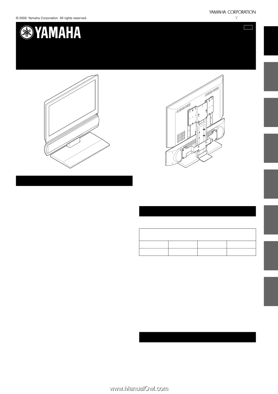
Compatible TV size: up to 52-inch, under 45 kg
*
Compliant with VESA Mounting Interface Standard and with the distance
between mounting holes described above.
The diameter of the screws should be up to 8 mm (the diameter of the supplied
screws are 5 mm, 6 mm, 8 mm).
Before installation, read the owner’s manual of your TV or measure
the distance of the mounting holes on the rear panel of your TV, and
check if your TV is possible to install. Note that even if the distance
of the mounting holes of your TV is the same as the distance
described above, there may be a case that you cannot install your TV
if there is a projection or input/output terminal in the way of the
bracket attachment area or if the bracket blocks the ventilation of the
TV.
This product is compatible with the following speaker models.
(As of October, 2009)
YSP-4000, YSP-5100/4100, YAS-81/71, YHT-S1400/S400
SAFETY PRECAUTION
COMPATIBLE TV
Compatible distance between mounting holes on the rear panel of the TV
(W × H)*
unit = cm
20 × 20
30 × 20
30 × 30
40 × 20
40 × 30
40 × 40
50 × 20
60 × 40
COMPATIBLE SPEAKER
G
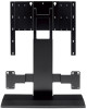
Integrated TV/Soundbar Pedestal
Socle intégré pour téléviseur et projecteur de son
YTS-T500
Install Manual
Manuel d’installation
Installationsanleitung
Installationsanvisningar
Printed in Malaysia
WU17410-1
Manuale d’installazione
Manual de instalación
Installatiehandleiding
Руководство по установке