ZyXEL VES1724-55C User Guide - Page 58
Table 7, Label, Description
 |
View all ZyXEL VES1724-55C manuals
Add to My Manuals
Save this manual to your list of manuals |
Page 58 highlights
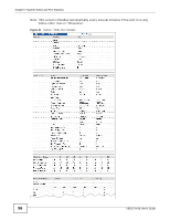
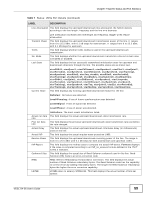
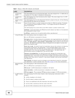
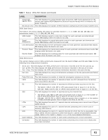
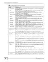
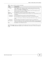
Chapter 7 System Status and Port Statistics The following table describes the labels in this screen. Table 7 Status: VDSL Port Details LABEL DESCRIPTION Port Info Number This field displays the selected port number. Name This field displays the descriptive name of the port. Link Type This field displays the type of the port. State This field displays whether the port is connected (Showtime), not connected (Idle), is searching for any CPE device (Handshake), is negotiating a connection with a CPE device (Training), is under loop diagnostic testing (LD_Testing), or has completed the loop diagnostic testing (LD_Done). See Section 7.2.1 on page 54 for more information. Up Time This field displays the total amount of time the line has been up. Actual Template This field displays the VDSL template the line is currently using. Transmission System This field displays the VDSL transmission mode the port is negotiating or has negotiated with the connected CPE device. Init Result This field displays the outcome of when the line was last initiated. The possible results are shown next. noFail: The initialization was successful. configError: The initialization failed because of a configuration error. configNotFeasible: The initialization failed because a setting is not supported on both the Switch and the CPE. commFail: The initialization failed because of a communication error between the Switch and the CPE. noPeerAtu: The initialization failed because the Switch cannot detect the connected CPE device. Limit Mask otherCause: The initialization failed because of another reason. To reduce the impact of interference and attenuation, ITU-T 993.2 specifies a limit PSD (Power Spectrum Density) mask that limits the VDSL2 transmitters' PSD for both downstream and upstream traffic. US0 Mask This field displays a standard-defined limit PSD mask that the line is currently using. This field displays the PSD mask used for upstream band 0. The possible masks are shown next. (See ITU-T G.993.2 Annex A for more information.) EU-32, EU-36, EU-40, EU-44, EU-48, EU-52, EU-56, EU-60, EU-64, EU-128 Electrical Length This field displays the final electrical length of the cable negotiated by the Switch and the connected CPE device. See UPBO/DPBO Electrical Length on page 100. Cyclic Extension Cyclic extension is a method that adds a redundant data into each DMT symbol. This helps to reduce interference on a line. VDSL Status Attainable net data rate SNR Margin Signal Attenuation This field displays the length of the redundant data used on the line. This parameter indicates the maximum upstream/downstream net data rate currently attainable by the Switch transmitter and the CPE receiver or by the CPE transmitter and the Switch receiver. This field displays the upstream/downstream SNR (Signal-to-Noise Rate) margin. This field displays the upstream/downstream loss of power (in dB) traveling along the line. 58 VES1724-56 User's Guide
-
 1
1 -
2
-
3
-
4
-
5
-
6
-
7
-
8
-
9
-
10
-
11
-
12
-
13
-
14
-
15
-
16
-
17
-
18
-
19
-
20
-
21
-
22
-
23
-
24
-
25
-
26
-
27
-
28
-
29
-
30
-
31
-
32
-
33
-
34
-
35
-
36
-
37
-
38
-
39
-
40
-
41
-
42
-
43
-
44
-
45
-
46
-
47
-
48
-
49
-
50
-
51
-
52
-
 53
53 -
 54
54 -
 55
55 -
 56
56 -
 57
57 -
 58
58 -
 59
59 -
 60
60 -
 61
61 -
 62
62 -
 63
63 -
64
-
65
-
66
-
67
-
68
-
69
-
70
-
71
-
72
-
73
-
74
-
75
-
76
-
77
-
78
-
79
-
80
-
81
-
82
-
83
-
84
-
85
-
86
-
87
-
88
-
89
-
90
-
91
-
92
-
93
-
94
-
95
-
96
-
97
-
98
-
99
-
100
-
101
-
102
-
103
-
104
-
105
-
106
-
107
-
108
-
109
-
110
-
111
-
112
-
113
-
114
-
115
-
116
-
117
-
118
-
119
-
120
-
121
-
122
-
123
-
124
-
125
-
126
-
127
-
128
-
129
-
130
-
131
-
132
-
133
-
134
-
135
-
136
-
137
-
138
-
139
-
140
-
141
-
142
-
143
-
144
-
145
-
146
-
147
-
148
-
149
-
150
-
151
-
152
-
153
-
154
-
155
-
156
-
157
-
158
-
159
-
160
-
161
-
162
-
163
-
164
-
165
-
166
-
167
-
168
-
169
-
170
-
171
-
172
-
173
-
174
-
175
-
176
-
177
-
178
-
179
-
180
-
181
-
182
-
183
-
184
-
185
-
186
-
187
-
188
-
189
-
190
-
191
-
192
-
193
-
194
-
195
-
196
-
197
-
198
-
199
-
200
-
201
-
202
-
203
-
204
-
205
-
206
-
207
-
208
-
209
-
210
-
211
-
212
-
213
-
214
-
215
-
216
-
217
-
218
-
219
-
220
-
221
-
222
-
223
-
224
-
225
-
226
-
227
-
228
-
229
-
230
-
231
-
232
-
233
-
234
-
235
-
236
-
237
-
238
-
239
-
240
-
241
-
242
-
243
-
244
-
245
-
246
-
247
-
248
-
249
-
250
-
251
-
252
-
253
-
254
-
255
-
256
-
257
-
258
-
259
-
260
-
261
-
262
-
263
-
264
-
265
-
266
-
267
-
268
-
269
-
270
-
271
-
272
-
273
-
274
-
275
-
276
-
277
-
278
-
279
-
280
-
281
-
282
-
283
-
284
-
285
-
286
-
287
-
288
-
289
-
290
-
291
-
292
-
293
-
294
-
295
-
296
-
297
-
298
-
299
-
300
-
301
-
302
-
303
-
304
-
305
-
306
-
307
-
308
-
309
-
310
-
311
-
312
-
313
-
314
-
315
-
316
-
317
-
318
-
319
-
320
-
321
-
322
-
323
-
324
-
325
-
326
-
327
-
328
-
329
-
330
-
331
-
332
-
333
-
334
-
335
-
336
-
337
-
338
-
339
-
340
-
341
-
342
-
343
-
344
-
345
-
346
-
347
-
348
-
349
-
350
-
351
-
352
-
353
-
354
-
355
-
356
-
357
-
358
-
359
-
360
-
361
-
362
-
363
-
364
-
365
-
366
-
367
-
368
-
369
-
370
-
371
-
372
-
373
-
374
-
375
-
376
-
377
-
378
-
379
-
380
-
381
-
382
-
383
-
384
-
385
-
386
-
387
-
388
-
389
-
390
-
391
-
392
-
393
-
394
-
395
-
396
-
397
-
398
-
399
-
400
-
401
-
402
-
403
-
404
-
405
-
406
-
407
-
408
-
409
-
410
-
411
-
412
-
413
-
414
 |
 |
