2009 Yamaha Motorsports V Star 250 Owners Manual - Page 71
2009 Yamaha Motorsports V Star 250 Manual

Page 71 highlights
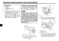
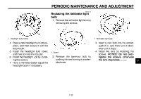
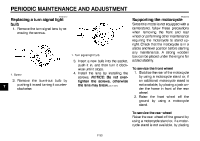
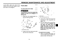
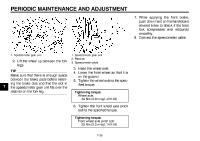
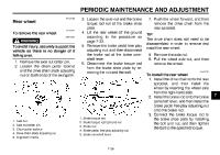
PERIODIC MAINTENANCE AND ADJUSTMENT EAU25080 Rear wheel EAU32751 To remove the rear wheel EWA10821 WARNING To avoid injury, securely support the vehicle so there is no danger of it falling over. 1. Remove the axle nut cotter pin. 2. Loosen the chain puller locknut and the drive chain slack adjusting nut on both ends of the swingarm. 3. Loosen the axle nut and the brake torque rod nut at the brake shoe plate. 4. Lift the rear wheel off the ground according to the procedure on page 7-33. 5. Remove the brake pedal free play adjusting nut, and then disconnect the brake rod at the brake camshaft lever. 6. Disconnect the brake torque rod from the brake shoe plate by removing the nut and the bolt. 7. Push the wheel forward, and then remove the drive chain from the rear sprocket. TIP The drive chain does not need to be disassembled in order to remove and install the rear wheel. 8. Remove the axle nut. 9. Pull the wheel axle out, and then remove the wheel. EAU32762 1. 2. 3. 4. 5. Axle nut Axle nut cotter pin Chain puller locknut Drive chain slack adjusting nut Alignment marks 1. 2. 3. 4. 5. Brake torque rod Brake torque rod bolt and nut Brake rod Brake pedal free play adjusting nut Brake camshaft lever To install the rear wheel 1. Install the drive chain onto the rear sprocket, and then install the wheel by inserting the wheel axle from the right-hand side. 2. Install the brake rod onto the brake camshaft lever, and then install the brake pedal free play adjusting nut onto the brake rod. 3. Connect the brake torque rod to the brake shoe plate by installing the bolt and nut, and then tighten the bolt to the specified torque. 7 7-36
-
 1
1 -
2
-
3
-
4
-
5
-
6
-
7
-
8
-
9
-
10
-
11
-
12
-
13
-
14
-
15
-
16
-
17
-
18
-
19
-
20
-
21
-
22
-
23
-
24
-
25
-
26
-
27
-
28
-
29
-
30
-
31
-
32
-
33
-
34
-
35
-
36
-
37
-
38
-
39
-
40
-
41
-
42
-
43
-
44
-
45
-
46
-
47
-
48
-
49
-
50
-
51
-
52
-
53
-
54
-
55
-
56
-
57
-
58
-
59
-
60
-
61
-
62
-
63
-
64
-
65
-
 66
66 -
 67
67 -
 68
68 -
 69
69 -
 70
70 -
 71
71 -
 72
72 -
 73
73 -
 74
74 -
 75
75 -
 76
76 -
77
-
78
-
79
-
80
-
81
-
82
-
83
-
84
-
85
-
86
-
87
-
88
-
89
-
90
-
91
-
92
-
93
-
94
 |
 |
