3Com 2126-G User Guide - Page 4
Mounting Kit Instructions Montagesatz Anweisungen Problem Solving - switch
 |
UPC - 662705494197
View all 3Com 2126-G manuals
Add to My Manuals
Save this manual to your list of manuals |
Page 4 highlights
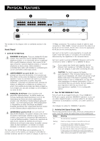
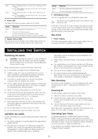
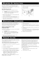
MOUNTING KIT INSTRUCTIONS The Switch is supplied with two mounting brackets and four screws. These are used for rack-mounting the unit. When mounting the unit, you should take note of the guidelines given in "Positioning the Switch" on page 3. Rack Mounting the Unit The Switch is 1U high and will fit a standard 19-inch rack. CAUTION: Disconnect all cables from the unit before continuing. Remove the self-adhesive pads from the underside of unit, if already fitted. 1 Place the unit the right way up on a hard, flat surface with the front facing towards you. 2 Locate a mounting bracket over the mounting holes on one side of the unit (refer to the figure following step 6). 3 Insert the two screws supplied in the mounting kit and fully tighten with a suitable screwdriver. 4 Repeat the two previous steps for the other side of the unit. 5 Insert the unit into the 19-inch rack and secure with suitable screws (not provided). 6 Reconnect all cables. MONTAGESATZ ANWEISUNGEN Der Switch wird mit zwei Halterungen und vier Schrauben geliefert. Diese werde für den Einbau in einen Baugruppenträger benutzt. Bei der Montage der Baugruppe beachten Sie die Anweisungen aus "Aufstellen des Switch" (page 3). Einbau der Baugruppen in einen Baugruppenträger Der Switch ist eine Baueinheit hoch und passt in einen Standard 19'' (Zoll) Baugruppenträger. ACHTUNG: Entfernen Sie alle Kabel, bevor Sie fortfahren. Entfernen Sie die selbstklebenden Polster (Füße) von der Unterseite der Baugruppe, falls diese bereits angebracht sind. 1 Plazieren Sie die Baugruppe aufrecht auf einer harten, ebenen Fläche mit der Vorderseite zu Ihnen. PROBLEM SOLVING 2 Ordnen Sie eine der Halterungen über den Löchern an der Seite der Baugruppe an. 3 Stecken Sie zwei der mitgelieferten Schrauben in die Löcher und drehen Sie diese mit einem geeigneten Schraubendreher fest. 4 Widerholen Sie letzten beiden Schritte auf der anderen Seite der Baugruppe. 5 Führen Sie die Baugruppe in den 19" (Zoll) Baugruppenträger ein und sichern sie die Baugruppe mit geeigneten Schrauben. (Nicht im Lieferumfang enthalten.) 6 Schließen Sie alle Kabel wieder an. Refer to the information about LEDs given earlier in this guide to see if the problem can be identified and rectified. Here are some common problems that can occur: Link Status LED not lit for a port that has a connection. There is a problem with this connection. Check that: „ The device being connected to is powered on and operating correctly. „ The cable is connected at both ends. „ The cable is not damaged. „ If the connection is to a workstation, that the workstation's network interface is installed and configured correctly. „ The correct category of cable is being used for the required link speed. Category 3 cables can be used for 10BASE-T operation only. Category 5 cables are required for 100BASE-TX or 1000BASE-T. 3Com recommends using Category 5e cables for 1000BASE-T operation. All ports appear to show continual activity. There may be broadcast storms on the network. Remove port connections one at a time, waiting a few seconds between each port. If the LEDs go off after removing a port connection, the device that was connected to that port is introducing an excessive amount of broadcast frames to the network (some pieces of network equipment operate by sending out broadcast frames regularly). Refer to the documentation that accompanies the device for information on disabling the broadcast operation. If the problem persists and the unit still does not operate successfully, contact your supplier with the following information before returning the unit: „ Product number and serial number (printed on a label supplied with the unit) „ A brief description of the fault 4
-
 1
1 -
 2
2 -
 3
3 -
 4
4 -
 5
5 -
 6
6 -
 7
7 -
 8
8 -
 9
9
 |
 |