3Com 3C13701 Installation Guide
3Com 3C13701 Manual
 |
View all 3Com 3C13701 manuals
Add to My Manuals
Save this manual to your list of manuals |
3Com 3C13701 manual content summary:
- 3Com 3C13701 | Installation Guide - Page 1
3Com® Router 5000 Family Installation Guide Router 5012 (3C13701) Router 5232 (3C13751) Router 5682 (3C13701) www.3Com.com Part Number: 10015619 Rev. AB Published: June 2007 - 3Com 3C13701 | Installation Guide - Page 2
to you in conjunction with, this User Guide. Unless otherwise indicated, 3Com registered trademarks are registered in the United States and may or may not be registered in other countries. 3Com and the 3Com logo are registered trademarks of 3Com Corporation. Cisco is a registered trademark of Cisco - 3Com 3C13701 | Installation Guide - Page 3
CONTENTS ABOUT THIS GUIDE Before You Start 5 Organization of the Manual 5 Conventions 5 Related Documentation 6 1 OVERVIEW Introduction 7 Types of SICs 9 Types of MIMs 9 2 SYSTEM SPECIFICATIONS 3Com Router Router 5012 11 3Com Router 5232 13 3Com Router Router 5682 15 3 INSTALLATION PREPARATION - 3Com 3C13701 | Installation Guide - Page 4
4 CONTENTS 6 ROUTER MAINTENANCE Software Maintenance 49 Hardware Maintenance 57 7 TROUBLESHOOTING Troubleshooting of the Power System 63 Troubleshooting of the Console Terminal 63 Troubleshooting of SDRAM 64 Application Software Upgrade 65 - 3Com 3C13701 | Installation Guide - Page 5
problems. You should read the Release Notes before installing the router in your network. If the information in the Release Notes differ from the information in this guide, follow the instructions in the Release Notes. Organization of the Manual The 3Com® Router 5000 Family Installation Guide - 3Com 3C13701 | Installation Guide - Page 6
6000 system. It is supplied in PDF format on the CD-ROM that accompanies the router. ■ 3Com® Router 5000/6000 Configuration Guide This guide contains information on the features supported by your router and how they can be used to optimize your network. It is supplied in PDF format on the CD-ROM - 3Com 3C13701 | Installation Guide - Page 7
3Com Corporation. Besides the benefit of simple configuration, the router provides rich network security features, and supports dumb terminal access, SNA (Systems Network Architecture)/DLSw (Data-Link Switching), IP multicast, ATM, MPLS and abundant QoS (Quality of Service) features. Thereby, 3Com - 3Com 3C13701 | Installation Guide - Page 8
CT1/PRI interface can connect the E1 or T1 interface of switches, as well as communicating with the gatekeeper (GK). With high-speed CPU and digital signal processing (DSP) technology, 3Com 5000 Routers can provide voice over IP (VoIP) services with high quality voice. They can drive down the cost - 3Com 3C13701 | Installation Guide - Page 9
SIC card (3C13726) ■ Router 1-port FXO SIC card (3C13727) ■ Router 2-port FXO SIC card (3C13728) Types of MIMs 3Com 5000 Router Family modular routers provide MIM slots for this release and support the following MIMs: Voice Modules ■ Router 2-port FXS MIM module (3C13780) ■ Router 2-port FXO MIM - 3Com 3C13701 | Installation Guide - Page 10
10 CHAPTER 1: OVERVIEW - 3Com 3C13701 | Installation Guide - Page 11
2 SYSTEM SPECIFICATIONS 3Com Router Router 5012 Appearance Figure 1 Front view of 3Com Router 5012 1) Power 3) SLOT1 5) SLOT3 7) LAN Figure 2 Rear view of 3Com Router 5012 2) SYSTEM 4) SLOT2 6) WAN 1) Power switch 3) Grounding screw 5) Console port (CON) 7) Fixed Ethernet interface (LAN) 9) SIC - 3Com 3C13701 | Installation Guide - Page 12
asynchronous serial interface LED: Show the status of data transceiving on the serial Description Table 3 System description of 3Com Router 5012 Item Slot Fixed interface CPU Boot ROM 5012 Two SIC slots One MIM slot One 10/100 Mbps Ethernet interface One WAN interface One AUX port One console - 3Com 3C13701 | Installation Guide - Page 13
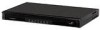
file. Boot ROM: Stores Bootstrap program. 3Com Router 5232 Appearance Figure 3 Front view of 3Com Router 5232 1) POWER 3) AUX 5) SLOT1~3 (READY/ACTIVE) Figure 4 Rear view of 3Com Router 5232 2) SYSTEM 4) CON 6) LAN (READY/ACTIVE) 1) Power switch 3) Grounding screw 5) Fixed WAN interface (WAN0 - 3Com 3C13701 | Installation Guide - Page 14
Table 5 System description of 3Com Router 5232 Item Fixed interface Slot CPU NVRAM Boot ROM SDRAM Flash Size (H x W x D) Weight Input voltage AC DC System power consumption Operation temperature Relative humidity (noncondensing) 5232 One AUX port One console - 3Com 3C13701 | Installation Guide - Page 15
5682 Appearance Figure 5 Front view of 3Com Router 5682 3Com Router Router 5682 15 1) POWER 3) AUX 5) SLOT0~7 (READY/ACTIVE) Figure 6 Rear view of 3Com Router 5682 2) SYSTEM 4) CON 1) Power switch 3) Grounding screw 5) MIM SLOT0 7) MIM SLOT3 9) MIM SLOT5 11) MIM SLOT7 2) Power socket 4) MIM - 3Com 3C13701 | Installation Guide - Page 16
powered on, ON means it is powered on. As for the router with RPS (3Com Router 5682), POWER lights when RPS works normally, POWER blinks when only The corresponding slot number. System Description Table 7 System description of 3Com Router 5682 Item Slot CPU NVRAM Boot ROM SDRAM Flash Size (H x - 3Com 3C13701 | Installation Guide - Page 17
greatest risk: for it will significantly degrade the router's reliability, speed up aging process of the insulating materials, and shorten the service life of the router. The requirements on the temperature and humidity for 3Com 5000 Routers are shown in Table 8: Table 8 Humidity requirements in - 3Com 3C13701 | Installation Guide - Page 18
SO2 0.2 H2S 0.006 NH3 0.05 Cl2 0.01 Requirements on Although many anti-static considerations have been given to 3Com 5000 Routers, Electrostatic damage to the router's circuit or even the whole equipment may still happen when the Discharge Prevention static electricity exceeds the tolerance - 3Com 3C13701 | Installation Guide - Page 19
interface modules of 3Com 5000 Routers are connected (such to install the router in the cabinet support the router and other installation accessories. ■ The cabinet and workbench are well grounded. Precautions Routers router router and any cable. ■ Correctly connect the interface cable for the router - 3Com 3C13701 | Installation Guide - Page 20
■ Ethernet cable ■ Interface cable for selected interface modules Devices ■ A Router, optional Multi-functional Interface Modules (MIMs) ■ Ethernet HUB or LAN Switch ■ CSU/DSU (channel service unit/data service unit) or other DCE devices ■ Console terminal (can be an ordinary PC) ■ Multimeter - 3Com 3C13701 | Installation Guide - Page 21
4 INSTALLATION OF THE ROUTER Installation Process Figure 7 3Com 5000 Router installation process Start Install the Router to the specified location Connect PGND Connect power cord Connect the Router to Console terminal Check Power on Troubleshooting No Normal? Yes Power off and disconnect the - 3Com 3C13701 | Installation Guide - Page 22
10cm around the router for heat dissipation. ■ Do not place heavy objects on the router. Installing the Router 3Com 5000 Routers are designed according of the router. 2 Put the router in a rack tray. Depending on the actual situation, slide the router along the chassis guides to an appropriate - 3Com 3C13701 | Installation Guide - Page 23
with the external network lines, such as E1/T1 line, ISDN/PSTN line. The grounding screw of 3Com 5000 Routers, which is marked with grounding label, is located near the AC power socket and its switch on the rear panel of the chassis, as shown in the following figure: Figure 9 Grounding screw of - 3Com 3C13701 | Installation Guide - Page 24
Connecting the Power Cord Two types of 3Com 5000 Routers are provided: ■ AC-powered ■ DC-powered Except for power socket for a AC-powered router: Figure 10 Partial external appearance of the power socket for the AC-powered router (1) Power switch (2) AC input receptacle Recommended Power - 3Com 3C13701 | Installation Guide - Page 25
Connecting the Power Cord 25 Connection of AC Power Cord 1 Confirm that the PGND wire is correctly connected. 2 Make sure that the power switch for the router is placed in the OFF position. Then, connect one end of the power cord, which came with the device, to the power socket on the - 3Com 3C13701 | Installation Guide - Page 26
-48V (1) (1) Main label Figure 14 DC power cord TO -48V 1 Confirm that the PGND wire has been correctly connected. 2 Make sure that the power switch of the router is in the OFF position. Then, connect one end of the DC power cord (including DC PGND connector and -48V power cord connector), which - 3Com 3C13701 | Installation Guide - Page 27
widely used. 2 Connect the cable. Turn the power switch off, then connect the DB9 serial interface of the console cable to the PC, and connect the RJ45 interface to the console port of the router. After the connection and verification, power on the router. Normally, the startup information of the - 3Com 3C13701 | Installation Guide - Page 28
4: INSTALLATION OF THE ROUTER Connecting Router to the LAN Introduction to the Ethernet Interface 3Com 5000 Routers provide fixed 100BASE-TX It is used to connect the terminal equipment, such as PCs and routers to HUBs or LAN Switches. ■ The wire sequences of the twisted pair wires crimped by the - 3Com 3C13701 | Installation Guide - Page 29
Switch. 2 Please check the LAN LED on front panel of the Router. ON means the link is connected. Connecting Router to the WAN 3Com 5000 Routers provide multiple types of WAN interfaces, and the fixed WAN interfaces include an AUX port and a WAN interface (synchronous/asynchronous serial interface - 3Com 3C13701 | Installation Guide - Page 30
connect the AUX cable: 1 Plug the RJ45 connector of the AUX cable into the AUX port of the router. 2 Connect the DB25 or DB9 connector of the AUX cable to the serial interface of the analog Modem. In general, the AUX port is used for remote configuration or dial-up backup. The local - 3Com 3C13701 | Installation Guide - Page 31
Interface to DSU/CSU Introduction to the Synchronous/Asynchronous Serial Interface. The fixed WAN interface of 3Com 5000 Routers is a synchronous/asynchronous serial interface, which is usually used for the connection with a WAN device, such as a Modem or CSU/DSU. It can operate in the synchronous - 3Com 3C13701 | Installation Guide - Page 32
, please refer to the manual that came with the device. Also the following table will be helpful in identifying DTE and DCE. Usually, the PC or Router serves as a DTE device and the Modem, Multiplexer or CSU/DSU serves as a DCE device. In general, the asynchronous serial interface is connected to - 3Com 3C13701 | Installation Guide - Page 33
Connecting Router to the WAN 33 The following figures show the cable assembly of all these types: ■ V.24 (RS232) DTE cable assembly Figure 18 V.24 (RS232) DTE cable assembly ■ V.24 (RS232) DCE cable assembly Figure 19 V.24 (RS232) DCE cable assembly - 3Com 3C13701 | Installation Guide - Page 34
34 CHAPTER 4: INSTALLATION OF THE ROUTER ■ V.35 DTE cable assembly Figure 20 V.35 DTE cable assembly ■ V.35 DCE cable assembly Figure 21 V.35 DCE cable assembly - 3Com 3C13701 | Installation Guide - Page 35
X.21 DTE cable assembly Connecting Router to the WAN 35 ■ X.21 DCE cable assembly Figure 23 X.21 DCE cable assembly The synchronous/asynchronous series interface matches a DB28 connector, and current these types of synchronous/asynchronous series interface cables are supported: ■ V.24 (RS232) DTE - 3Com 3C13701 | Installation Guide - Page 36
36 CHAPTER 4: INSTALLATION OF THE ROUTER ■ V.24 DCE cable assembly Figure 25 V.24 DCE cable assembly ■ V.35 DTE cable assembly Figure 26 V.35 DTE cable assembly ■ V.35 DCE cable assembly Figure 27 V.35 DCE cable assembly ■ X.21 DTE cable assembly Figure 28 X.21 DTE cable assembly - 3Com 3C13701 | Installation Guide - Page 37
DB50 connector of the cable into the interface WAN on the router. 3 Connect the other end of the cable to the CSU/DSU device. If the WAN adopts dial-up line, connect the cable to the serial interface of the analog modem. Connecting E1 Interface to DSU/CSU Introduction to the E1 Interface - 3Com 3C13701 | Installation Guide - Page 38
twisted pair cable The cable is attached with DB15 (male) connector for the router end, and with RJ45 connector for the network end. See the following figure Switch Impedance inverter switch is also available, through which you can choose the interface impedance value. ■ Turn on the switch to - 3Com 3C13701 | Installation Guide - Page 39
possible damage. 1 Check the E1 cable type and choose correct impedance value of the E1 interface through the inverter switch. 2 Insert the DB15 connector into the E1 interface of the router. 3 Connect the other end to the right network devices. ■ For 75Ω unbalanced coax cable Connect the cable in - 3Com 3C13701 | Installation Guide - Page 40
40 CHAPTER 4: INSTALLATION OF THE ROUTER If you choose two RJ45 connectors (for extending shielded cable) T1, CT1, ISDN PRI Backup Terminal access ISDN For the T1 module, corresponding serial interface shall be created after you use the timeslot bundling command on the Controller T1 interface. - 3Com 3C13701 | Installation Guide - Page 41
Examine the interface mark before connection to avoid cable mis-insertion and router damage. ■ When the T1 interface cable is routed outdoors, you . 1 Insert one end of the T1 interface cable into the E1 interface of the router. 2 Insert the other end to the peer device. ■ If one cable is enough - 3Com 3C13701 | Installation Guide - Page 42
the power cord connects to is compliant with that required by the router. ■ Whether the PGND wire of the router is correctly connected. ■ Whether the router is correctly connected to other devices, such as the console terminal. CAUTION: The check after installation is very important. The stability - 3Com 3C13701 | Installation Guide - Page 43
, the RJ-45 connector of the console cable needs to be connected to the console port on the router, and the DB-25 or DB-9 connector to the serial interface of a PC. Setting the Parameters for Console Terminal Opening the Console Terminal and Setting Up a New Connection If the configuration - 3Com 3C13701 | Installation Guide - Page 44
1 Select a connection port. Select the serial interface to be connected in the [Connect using] box, as shown in Figure 37. Please note that the selected serial interface should be consistent with the actual serial interface connected by the console cable. Figure 37 Setting the connection port in the - 3Com 3C13701 | Installation Guide - Page 45
with the requirement of the router. ■ Whether the console cable is correctly connected, whether the PC or terminal for configuration is open, and whether the settings are done. WARNING: Before powering on the router, be aware of where the power supply switch to the router is located, so that the - 3Com 3C13701 | Installation Guide - Page 46
is normal The startup interface on the console terminal can be seen after the router is powered on (please see "Startup Process" in this manual for reference). After the startup (in other words, self-test), you are prompted to press . When "" is displayed, you can proceed to configure - 3Com 3C13701 | Installation Guide - Page 47
This prompt indicates that the router has entered the system view, and now the router can be configured. Configuration Fundamentals of the Router Basic WAN interface of the router. First, configure the physical operating parameters (e.g., the operating mode of the serial interface, baud rate - 3Com 3C13701 | Installation Guide - Page 48
The command line interface of 3Com 5000 Routers provide plenty of configuration commands. Hierarchical user protection is adopted to prevent unauthorized users from illegal invading. Each group corresponds to a view. These commands can be used to switch - 3Com 3C13701 | Installation Guide - Page 49
Boot ROM image through XMODEM ■ Upgrading the application image through TFTP ■ Uploading/downloading the application image and configuration file through FTP 3Com 5000 Routers are loaded initially. You may need to upgrade it and its corresponding Boot ROM image to accommodate new product features - 3Com 3C13701 | Installation Guide - Page 50
Boot Menu Start the router; when the message "Press Ctrl-B to enter Boot Menu appears, press . The console screen displays: Please input Parameter 2: Download From Net 3: Exit to Main Menu Enter your choice(1-3):1 3 Set the type of the application image file to change the type of a boot file - 3Com 3C13701 | Installation Guide - Page 51
that, you need to download it again. Select in Boot Menu. The console screen displays the following menu, provided four application image files have existed in Flash change the file type of a.bin. The console screen displays: Set this file as: 1. Main 2. Backup 3. Exit Enter your choice(1-3): 1 - 3Com 3C13701 | Installation Guide - Page 52
6: ROUTER MAINTENANCE To use a.bin as the main boot file, select in this menu. Upon validation of the setting, the file type of the original main boot file changes to N/A. Now, the a.bin file is the first boot file. 4 Display applications in Flash memory. Select in Boot Menu. The console - 3Com 3C13701 | Installation Guide - Page 53
available with the router: Please choose your download speed: 1: 9600 bps 2: 19200 bps 3: 38400 bps 4: 57600 bps 5: 115200 bps 6: Exit and reboot Enter your choice(1-6): 2 Select an appropriate download speed, for 115200 bps for example. The console screen displays: Download speed is 115200 bps - 3Com 3C13701 | Installation Guide - Page 54
54 CHAPTER 6: ROUTER MAINTENANCE To validate the new baud rate set on the console terminal, you must disconnect and then and upon its completion outputs the following information: Download completed. For an 3Com 5000 router, the system also prompts you to select file type upon completion of - 3Com 3C13701 | Installation Guide - Page 55
the Boot ROM image through XMODEM. Multiple download speeds are available. The subsequent steps are the Enter . For a successful backup, the console screen displays: Writing to FLASH.Please wait Menu appears again, select to and reboot the router. 2 Restore the extended segment of the Boot ROM - 3Com 3C13701 | Installation Guide - Page 56
using a fixed Ethernet interface. CAUTION: No TFTP/FTP Server is available with the 3Com 5000 Routers. You must install one yourself. 1 Start TFTP or FTP Server on the PC connected to the Ethernet interface on the router and set the path for getting the source file. Given FTP Server, you need to - 3Com 3C13701 | Installation Guide - Page 57
to return to Net Port Download Menu, and there select . The console screen displays: boot device : fei unit number : 0 processor number : 0 host Required Tools Installation tools are not provided with the 3Com 5000 Routers. You must have the following tools available. ■ - 3Com 3C13701 | Installation Guide - Page 58
cover 3) Fastening screw 2) Chassis bottom CAUTION: ■ On a mounting screw of your router chassis, there is an anti-dismantle seal of 3Com Corporation. You must keep it in good condition when asking your sales agent for servicing. You can open the chassis yourself but with permission of your sales - 3Com 3C13701 | Installation Guide - Page 59
. ■ The existing SDRAM is damaged. You can see this banner at boot: Router starts booting ... (V2.00) * * * 3Com 5000 Routers Boot ROM, V9.13 * * * Copyright(C) 1997-2003 by 3Com Corporation. Testing memory...OK! 128M bytes DDR SDRAM 32768K bytes flash memory Hardware Version is - 3Com 3C13701 | Installation Guide - Page 60
MAINTENANCE Where, "128M bytes SDRAM" means that the router is installed with a 128 MB SDRAM. There is a limit on the times that you can install the both of the memory slots slot The following figure shows the position of the SDRAM on the 3Com Router. Figure 42 Position of the SDRAM on the - 3Com 3C13701 | Installation Guide - Page 61
Hardware Maintenance 61 The following figure shows the position of the SDRAM on the 3Com Router 5232. Figure 43 Position of the SDRAM on the 3Com 5232 To ensure you can install the SDRAM correctly, there are two clips In the SDRAM slot matching two concave points in the SDRAM card. - 3Com 3C13701 | Installation Guide - Page 62
the Chassis Cover CAUTION: Roll up all the cables inside the router and put them into the chassis before closing the chassis cover, preventing them from engage with the front panel of the chassis. 4 Put the whole cover onto the router base, until the tabs on the side edges of the cover engage with the side - 3Com 3C13701 | Installation Guide - Page 63
Displays Fault: After POST After the POST of the router, the terminal does not display any information. Troubleshooting: 1 Check: ■ Whether the power system is normal. ■ Whether the console cable is connected correctly. 2 If no problems are found after performing the above checks, it is likely - 3Com 3C13701 | Installation Guide - Page 64
router, despite the normal power system (the POWER LED is ON) and proper connection of the console cable, there is no display on the console terminal. Troubleshooting: If you are sure that the power system and configuration system have no faults, please contact the agent of 3Com Corporation problem - 3Com 3C13701 | Installation Guide - Page 65
extension) of the application software set on the Router are correct. Upgrade the application software again after the problem is solved. Fault 2: key when ready. Troubleshooting: 3Com 5000 Routers should be loaded with different application software versions. The problem described above is likely - 3Com 3C13701 | Installation Guide - Page 66
66 CHAPTER 7: TROUBLESHOOTING If the improper software has been loaded, the Router cannot start or work correctly. In the software with other approaches, solve the problem with reference to this example. The bar code labeled on the Router host and the MIM contains the relevant manufacturing
-
 1
1 -
 2
2 -
 3
3 -
 4
4 -
 5
5 -
 6
6 -
 7
7 -
8
-
9
-
10
-
11
-
12
-
13
-
14
-
15
-
16
-
17
-
18
-
19
-
20
-
21
-
22
-
23
-
24
-
25
-
26
-
27
-
28
-
29
-
30
-
31
-
32
-
33
-
34
-
35
-
36
-
37
-
38
-
39
-
40
-
41
-
42
-
43
-
44
-
45
-
46
-
47
-
48
-
49
-
50
-
51
-
52
-
53
-
54
-
55
-
56
-
57
-
58
-
59
-
60
-
61
-
62
-
63
-
64
-
65
-
66
 |
 |

3Com
®
Router 5000 Family
Installation Guide
Router 5012 (3C13701)
Router 5232 (3C13751)
Router 5682 (3C13701)
www.3Com.com
Part Number: 10015619 Rev. AB
Published: June 2007