3Com 4200G Installation Guide - Page 3
XENPAK Optical Module - me
 |
UPC - 662705505671
View all 3Com 4200G manuals
Add to My Manuals
Save this manual to your list of manuals |
Page 3 highlights
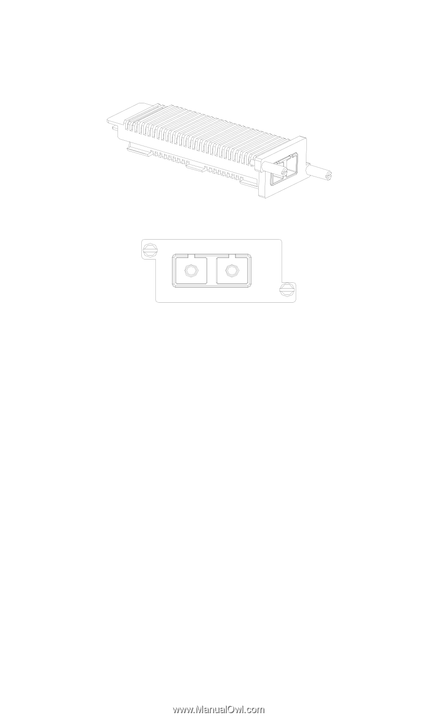
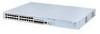
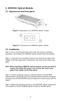
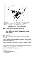
2. XENPAK Optical Module 2.1 Appearance and front panel Figure 4 Appearance of a XENPAK optical module Figure 5 Front panel of a XENPAK optical module 2.2 Installation Step 1: Put on an ESD-preventive wrist strap and verify it is properly grounded. Then remove the XENPAK optical module from the package. Step 2: Loosen the two mounting screws on the small cover plate in the middle on the filler panel with a screwdriver and remove the small cover plate. Note: When installing a XENPAK optical module, you do not need to remove the entire filler panel. Just remove the small cover plate in the middle on the filler panel. Step 3: Hold the fastening screws on the front panel of the XENPAK optical module, and gently push the XENPAK optical module in along the slot guide rail until the XENPAK optical module is in close contact with the switch. Step 4: Tighten the fastening screws on the XENPAK optical module with a screwdriver to fix the XENPAK optical module on the filler panel. 3
-
 1
1 -
 2
2 -
 3
3 -
 4
4
 |
 |