3Ware RDC-TRAY Quick Start Guide - Page 2
B, QUICK START GUIDE, 3W-RDC-400 Rev March 2003, of 4 - inc
 |
UPC - 693494990058
View all 3Ware RDC-TRAY manuals
Add to My Manuals
Save this manual to your list of manuals |
Page 2 highlights
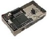
2. Connect the cables as shown in figure 2. When connecting cables to the IDE bus make sure the numerical pins are lined up with the connector, else you may damage the hard disk drive. Figure 2 Installing a hard drive in the disk tray 1. Remove an empty disk tray. 2. Unpack the hard drive. Set the HDD to "Master". Refer to the manufacturer's documentation for the location of this jumper . CAUTION: Static electrical discharge (ESD) can damage your drive or other components. To avoid ESD, ground yourself by touching any metal on the subsystem chassis. 3. Connect the power cable to the power connector on the hard drive. 4. Connect the 40-pin ATA cable to the IDE connector on the hard drive. Align the colored edge of the cable with pin 1 of the connector. 720-0091-00 B QUICK START GUIDE, 3W-RDC-400 Rev March 2003 Downloaded from www.Manualslib.com manuals search engine Page 2 of 4
-
 1
1 -
 2
2 -
 3
3 -
 4
4
 |
 |
