AIWA CDC-Z107 Service Manual - Page 24
AIWA CDC-Z107 Manual
 |
View all AIWA CDC-Z107 manuals
Add to My Manuals
Save this manual to your list of manuals |
Page 24 highlights
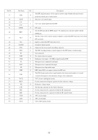
Pin No. 48 49 50 51 52 53 54 55 56 57 58 ~ 60 61 62 63 64 65 66 67 68 69 70 71 72 73 74 75 76 77 78 79 80 Pin Name RWC CD RES SW3 SW2 SW1 R-ENCOD2 R-ENCOD1 LCD-DI REMOTE IN LED NC INSIDE TEST NC L IND PH.MUTE RESET HOLD SNS NC IF EO3 SUBPD VDD AM OSC FM OSC VSS EO2 EO1 NC XOUT I/O Description O Read / write control output terminal. O DSP reset output terminal. I Disc detection / chuck or release disc detection. I 12 cm disc detection / 12 cm disc ejection end detection. I Leading motor start detection. I Rotary encoder input 2. I Rotary encoder input 1. I LCD driver data signal input. I Remote controller input. Pulled up when not used. O Security LED flashing output. H: No light on, L: Light on. - Not connected. I Pick up inner track position detection. I CD test mode. Pulled down when not used. - Not connected. I Voltage input for level indecator. Pulled down when not used. I External mute control. Low=-20dB mute. Pulled up when not used. I System reset. Low= system reset. I ACC (accessory power) ON/ OFF input. OFF=fault mode. I Backup detection. - Not connected. I IF count signal input (FM / AM). - Not used. - Not used. - Power supply. I AM channel transmission input. I FM channel transmission input. - Connected to GND. O Not used. O Error out from charge pump (for FM / AM). - Not connected. O System clock oscillator output. - 24 -
-
 1
1 -
2
-
3
-
4
-
5
-
6
-
7
-
8
-
9
-
10
-
11
-
12
-
13
-
14
-
15
-
16
-
17
-
18
-
 19
19 -
 20
20 -
 21
21 -
 22
22 -
 23
23 -
 24
24 -
 25
25 -
 26
26 -
 27
27 -
 28
28 -
 29
29 -
30
-
31
-
32
-
33
-
34
-
35
-
36
 |
 |
