ASRock 2Core1333DVI-2.66G Quick Installation Guide - Page 13
English, Installing a DIMM
 |
View all ASRock 2Core1333DVI-2.66G manuals
Add to My Manuals
Save this manual to your list of manuals |
Page 13 highlights
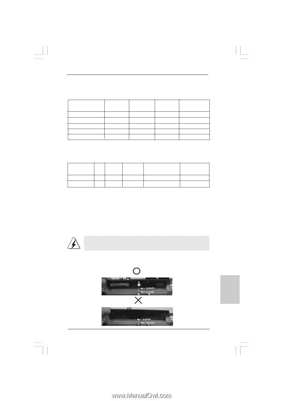
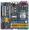
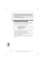
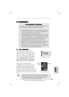
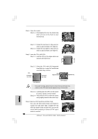
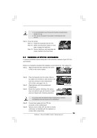
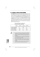
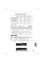
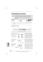
Recommended Memory Configurations (DS: Double Side, SS: Single Side) DDRII_1 DDRII_2 DDRII_3 DDRII_4 (Yellow Slot) (Orange Slot) (Yellow Slot) (Orange Slot) 1 memory module DS/SS* X X X 2 memory modules DS/SS X DS/SS X 2 memory modules X DS/SS X DS/SS 3 memory modules SS SS DS/SS X 4 memory modules SS SS SS SS * If you only install one memory module, you can install it to any one of the four slots. These two TRANSCEND memory modules can only be supported under the following conditions: DRAM SIZE TYPE CELL CELL NO. SINGLE SIDE / VENDOR (MB) VENDOR DOUBLE SIDE TRANSCEND 256 DDRII533 SAMSUNG K4T56083QF-ZCD5 SINGLE SIDE TRANSCEND 512 DDRII533 INFINEON HYB18T512800AF37 SINGLE SIDE 1. If you plan to install one above memory module, you can install it to any DDRII slot of this motherboard. 2. If you plan to install two above memory modules, it is recommended to install them either in the set of yellow slots (DDRII_1 and DDRII_3), or in the set of orange slots (DDRII_2 and DDRII_4). 3. This motherboard does not support three or four above memory modules. Installing a DIMM Please make sure to disconnect power supply before adding or removing DIMMs or the system components. Step 1. Unlock a DIMM slot by pressing the retaining clips outward. Step 2. Align a DIMM on the slot such that the notch on the DIMM matches the break on the slot. English 13 ASRock 2Core1333DVI-2.66G Motherboard
-
 1
1 -
2
-
3
-
4
-
5
-
6
-
7
-
 8
8 -
 9
9 -
 10
10 -
 11
11 -
 12
12 -
 13
13 -
 14
14 -
 15
15 -
 16
16 -
 17
17 -
 18
18 -
19
-
20
-
21
-
22
-
23
-
24
-
25
-
26
-
27
-
28
-
29
-
30
-
31
-
32
-
33
-
34
-
35
-
36
-
37
-
38
-
39
-
40
-
41
-
42
-
43
-
44
-
45
-
46
-
47
-
48
-
49
-
50
-
51
-
52
-
53
-
54
-
55
-
56
-
57
-
58
-
59
-
60
-
61
-
62
-
63
-
64
-
65
-
66
-
67
-
68
-
69
-
70
-
71
-
72
-
73
-
74
-
75
-
76
-
77
-
78
-
79
-
80
-
81
-
82
-
83
-
84
-
85
-
86
-
87
-
88
-
89
-
90
-
91
-
92
-
93
-
94
-
95
-
96
-
97
-
98
-
99
-
100
-
101
-
102
-
103
-
104
-
105
-
106
-
107
-
108
-
109
-
110
-
111
-
112
-
113
-
114
-
115
-
116
-
117
 |
 |