ASRock 990FX Extreme6 User Manual - Page 26
ATX 12V Power
 |
View all ASRock 990FX Extreme6 manuals
Add to My Manuals
Save this manual to your list of manuals |
Page 26 highlights
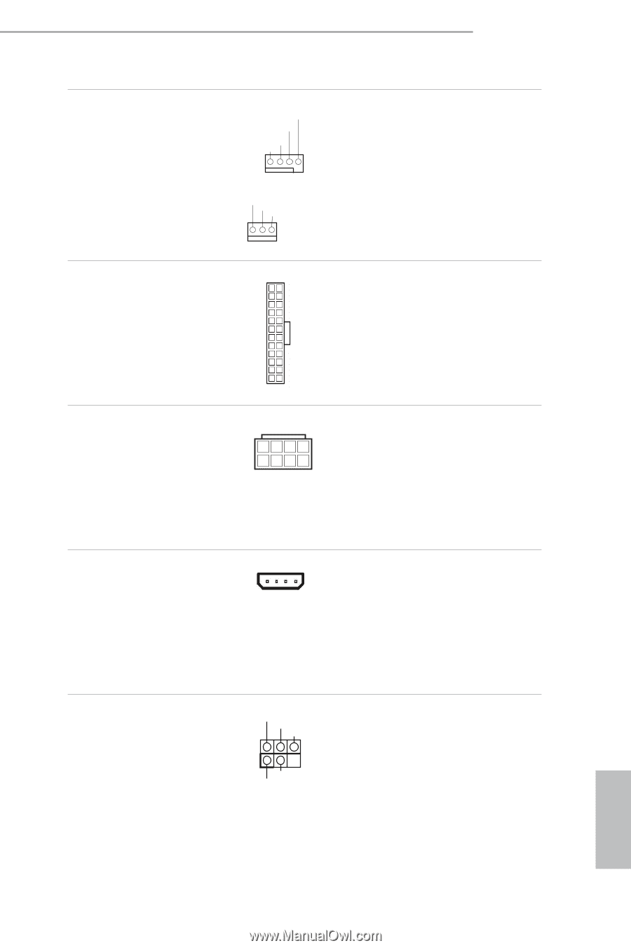
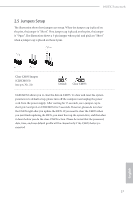
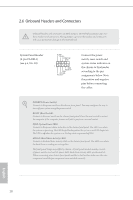
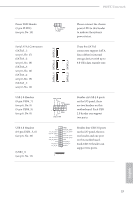
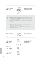
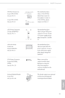
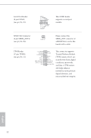
990FX Extreme6 CPU Fan Connectors (4-pin CPU_FAN1) (see p.6, No. 3) (3-pin CPU_FAN2) (see p.6, No. 4) FAN_SPEED_CONTROL CPU_FAN_SPEED +12V GND 1 2 3 4 GND +12V CPU_FAN_SPEED his motherboard provides a 4-Pin CPU fan (Quiet Fan) connector. If you plan to connect a 3-Pin CPU fan, please connect it to Pin 1-3. ATX Power Connector (24-pin ATXPWR1) (see p.6, No. 7) ATX 12V Power Connector (8-pin ATX12V1) (see p.6, No. 2) PCIe Power Connector (4-pin SLI/XFIRE_ PWR1) (see p.6, No. 23) Infrared Module Header (5-pin IR1) (see p.6, No. 24) 12 24 1 13 8 5 4 1 IRTX +5VSB DUMMY 1 GND IRRX his motherboard provides a 24-pin ATX power connector. To use a 20-pin ATX power supply, please plug it along Pin 1 and Pin 13. his motherboard provides an 8-pin ATX 12V power connector. To use a 4-pin ATX power supply, please plug it along Pin 1 and Pin 5. Please connect this connector with a hard disk power connector when three graphics cards are installed on this motherboard. his header supports an optional wireless transmitting and receiving infrared module. English 21
-
 1
1 -
2
-
3
-
4
-
5
-
6
-
7
-
8
-
9
-
10
-
11
-
12
-
13
-
14
-
15
-
16
-
17
-
18
-
19
-
20
-
 21
21 -
 22
22 -
 23
23 -
 24
24 -
 25
25 -
 26
26 -
 27
27 -
 28
28 -
 29
29 -
 30
30 -
 31
31 -
32
-
33
-
34
-
35
-
36
-
37
-
38
-
39
-
40
-
41
-
42
-
43
-
44
-
45
-
46
-
47
-
48
-
49
-
50
-
51
-
52
-
53
-
54
-
55
-
56
-
57
-
58
-
59
-
60
-
61
-
62
-
63
-
64
-
65
-
66
-
67
-
68
-
69
-
70
-
71
-
72
-
73
-
74
 |
 |