ASRock 990FX Extreme9 User Guide - Page 33
English, The Installation Guide of Rear USB 3.0 Bracket, Smart Switches
 |
View all ASRock 990FX Extreme9 manuals
Add to My Manuals
Save this manual to your list of manuals |
Page 33 highlights
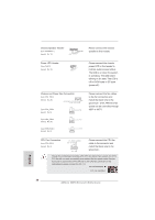
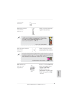
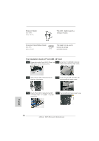
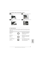
The Installation Guide of Rear USB 3.0 Bracket Step 1 Unscrew the two screws from the Front USB 3.0 Step 2 Put the USB 3.0 cable and the rear Panel. USB 3.0 bracket together. Step 3 Screw the two screws into the rear USB 3.0 bracket. Step 4 Put the rear USB 3.0 bracket into the chassis. 2.9 Smart Switches The motherboard has three smart switches: power switch, reset switch and clear CMOS switch, allowing users to quickly turn on/off or reset the sytem clear the CMOS values. Power Switch (PWRBTN) (see p.2 No. 21) Power Power Switch is a smart switch, allowing users to quickly turn on/off the system. Reset Switch (RSTBTN) (see p.2 No. 22) Reset Switch is a smart switch, allowing users to quickly reset Reset the system. Clear CMOS Switch (CLRCBTN) (see p.3 No. 18) clr CMOS Clear CMOS Switch is a smart switch, allowing users to quickly clear the CMOS values. 33 ASRock 990FX Extreme9 Motherboard English
-
 1
1 -
2
-
3
-
4
-
5
-
6
-
7
-
8
-
9
-
10
-
11
-
12
-
13
-
14
-
15
-
16
-
17
-
18
-
19
-
20
-
21
-
22
-
23
-
24
-
25
-
26
-
27
-
 28
28 -
 29
29 -
 30
30 -
 31
31 -
 32
32 -
 33
33 -
 34
34 -
 35
35 -
 36
36 -
 37
37 -
 38
38 -
39
-
40
-
41
-
42
-
43
-
44
-
45
-
46
-
47
-
48
-
49
-
50
-
51
-
52
-
53
-
54
-
55
-
56
-
57
-
58
-
59
-
60
-
61
-
62
-
63
-
64
-
65
-
66
-
67
-
68
-
69
-
70
-
71
-
72
-
73
-
74
-
75
-
76
-
77
-
78
-
79
-
80
-
81
-
82
-
83
-
84
-
85
-
86
-
87
-
88
-
89
-
90
-
91
-
92
-
93
-
94
-
95
-
96
-
97
-
98
-
99
-
100
-
101
-
102
-
103
-
104
-
105
-
106
-
107
-
108
-
109
-
110
-
111
-
112
-
113
-
114
-
115
-
116
-
117
-
118
-
119
-
120
-
121
-
122
-
123
-
124
-
125
-
126
-
127
-
128
-
129
-
130
-
131
-
132
-
133
-
134
-
135
-
136
-
137
-
138
-
139
-
140
-
141
-
142
-
143
-
144
-
145
-
146
-
147
-
148
-
149
-
150
-
151
-
152
-
153
-
154
-
155
-
156
-
157
-
158
-
159
-
160
-
161
-
162
-
163
-
164
-
165
-
166
-
167
-
168
-
169
-
170
-
171
-
172
-
173
-
174
-
175
-
176
-
177
-
178
-
179
-
180
-
181
-
182
-
183
-
184
-
185
-
186
-
187
-
188
-
189
-
190
-
191
-
192
-
193
 |
 |
