ASRock A620M Pro RS User Manual - Page 42
Power LED and Speaker Header
 |
View all ASRock A620M Pro RS manuals
Add to My Manuals
Save this manual to your list of manuals |
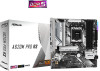
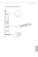
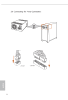
Page 42 highlights
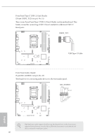
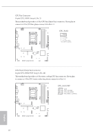
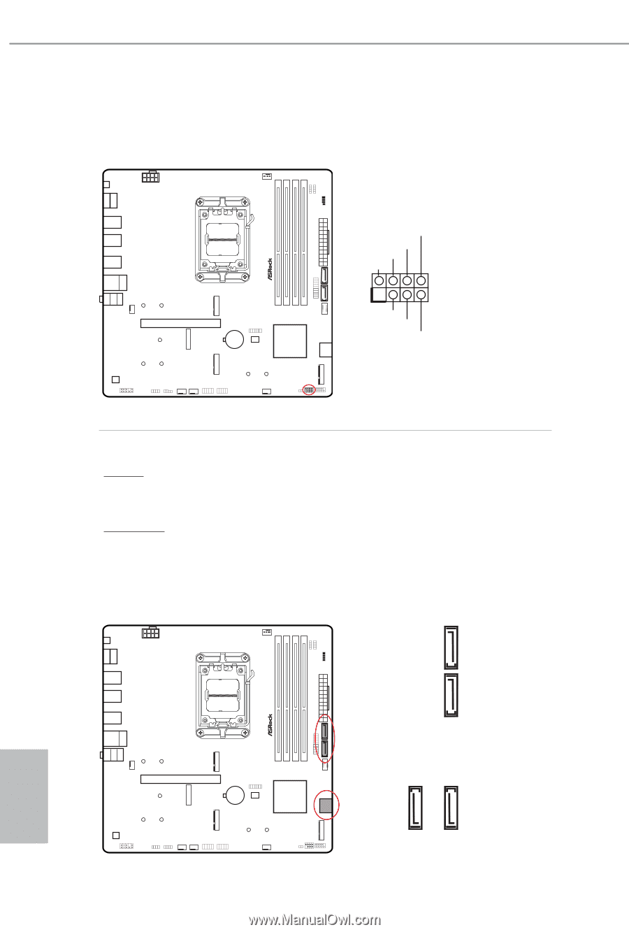
Power LED and Speaker Header (7-pin SPK_PLED1) (see p.6, No. 16) Please connect the chassis power LED and the chassis speaker to this header. SPK_PLED1 SPEAKER DUMMY DUMMY +5V 1 PLED+ PLED+ PLED- Serial ATA3 Connectors Vertical: (SATA3_1) (see p.6, No. 9) (SATA3_2) (see p.6, No. 10) Right Angle: (SATA3_3) (see p.6, No. 14) (Lower) (SATA3_4) (see p.6, No. 14) (Upper) These four SATA3 connectors support SATA data cables for internal storage devices with up to 6.0 Gb/s data transfer rate. 38 SATA3_2 SATA3_1 SATA3_4 SATA3_3 English
-
 1
1 -
2
-
3
-
4
-
5
-
6
-
7
-
8
-
9
-
10
-
11
-
12
-
13
-
14
-
15
-
16
-
17
-
18
-
19
-
20
-
21
-
22
-
23
-
24
-
25
-
26
-
27
-
28
-
29
-
30
-
31
-
32
-
33
-
34
-
35
-
36
-
 37
37 -
 38
38 -
 39
39 -
 40
40 -
 41
41 -
 42
42 -
 43
43 -
 44
44 -
 45
45 -
 46
46 -
 47
47 -
48
-
49
-
50
-
51
-
52
-
53
-
54
-
55
-
56
-
57
-
58
-
59
-
60
-
61
-
62
-
63
-
64
-
65
-
66
-
67
 |
 |
English
38
Power LED and Speaker Header
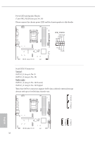
(7-pin SPK_PLED1) (see p.6, No. 16)
Please connect the chassis power LED and the chassis speaker to this header.
Serial ATA3 Connectors
Vertical:
(SATA3_1) (see p.6, No. 9)
(SATA3_2) (see p.6, No. 10)
Right Angle:
(SATA3_3) (see p.6, No. 14) (Lower)
(SATA3_4) (see p.6, No. 14) (Upper)
°ese four SATA3 connectors support SATA data cables for internal storage
devices with up to 6.0 Gb/s data transfer rate.
1
+5V
DUMMY
PLED+
PLED+
PLED-
DUMMY
SPEAKER
SPK_PLED1
SATA3_1
SATA3_4
SATA3_2
SATA3_3