ASRock B450M Pro4 Quick Installation Guide - Page 38
Step 3, Step 4, Step 5, Step 6
 |
View all ASRock B450M Pro4 manuals
Add to My Manuals
Save this manual to your list of manuals |
Page 38 highlights
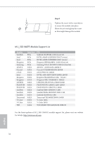
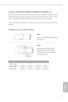
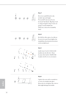
D C B A D C B A Step 3 Move the standoff based on the module type and length. The standoff is placed at the nut location D by default. Skip Step 3 and 4 and go straight to Step 5 if you are going to use the default nut. Otherwise, release the standoff by hand. Step 4 Peel off the yellow protective film on the nut to be used. Hand tighten the standoff into the desired nut location on the motherboard. Step 5 Gently insert the M.2 (NGFF) SSD module into the M.2 slot. Please be aware that the M.2 (NGFF) SSD module only fits in one orientation. English D NUT2 NUT1 36 Step 6 Tighten the screw with a screwdriver to secure the module into place. Please do not overtighten the screw as this might damage the module.
-
 1
1 -
2
-
3
-
4
-
5
-
6
-
7
-
8
-
9
-
10
-
11
-
12
-
13
-
14
-
15
-
16
-
17
-
18
-
19
-
20
-
21
-
22
-
23
-
24
-
25
-
26
-
27
-
28
-
29
-
30
-
31
-
32
-
 33
33 -
 34
34 -
 35
35 -
 36
36 -
 37
37 -
 38
38 -
 39
39 -
 40
40 -
 41
41 -
 42
42 -
 43
43 -
44
-
45
-
46
-
47
-
48
-
49
-
50
-
51
-
52
-
53
-
54
-
55
-
56
-
57
-
58
-
59
-
60
-
61
-
62
-
63
-
64
-
65
-
66
-
67
-
68
-
69
-
70
-
71
-
72
-
73
-
74
-
75
-
76
-
77
-
78
-
79
-
80
-
81
-
82
-
83
-
84
-
85
-
86
-
87
-
88
-
89
-
90
-
91
-
92
-
93
-
94
-
95
-
96
-
97
-
98
-
99
-
100
-
101
-
102
-
103
-
104
-
105
-
106
-
107
-
108
-
109
-
110
-
111
-
112
-
113
-
114
-
115
-
116
-
117
-
118
-
119
-
120
-
121
-
122
-
123
-
124
-
125
-
126
-
127
-
128
-
129
-
130
-
131
-
132
-
133
-
134
-
135
-
136
-
137
-
138
-
139
-
140
-
141
-
142
-
143
-
144
-
145
-
146
-
147
-
148
-
149
-
150
-
151
-
152
-
153
-
154
-
155
-
156
-
157
-
158
-
159
-
160
-
161
-
162
-
163
-
164
-
165
-
166
-
167
-
168
-
169
-
170
-
171
-
172
-
173
-
174
-
175
-
176
-
177
-
178
-
179
-
180
-
181
-
182
-
183
 |
 |

English
36
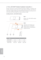
Step 3
Move the stando´ based on the
module type and length.
Te stando´ is placed at the nut
location D by default. Skip Step 3 and
4
and go straight to Step
5
if you are
going to use the default nut.
Otherwise, release the stando´ by
hand.
B
C
D
A
Step 4
Peel o´ the yellow protective Flm on
the nut to be used. Hand tighten the
stando´ into the desired nut location
on the motherboard.
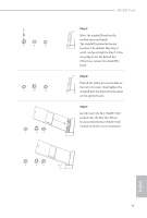
Step 5
Gently insert the M.2 (NG²²) SSD
module into the M.2 slot. Please
be aware that the M.2 (NG²²) SSD
module only Fts in one orientation.
NUT1
NUT2
D
Step 6
³ighten the screw with a screwdriver
to secure the module into place.
Please do not overtighten the screw as
this might damage the module.
B
C
D
A