ASRock B560M Pro4 User Manual - Page 31
Caution: Never install the RGB
 |
View all ASRock B560M Pro4 manuals
Add to My Manuals
Save this manual to your list of manuals |
Page 31 highlights
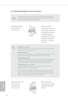
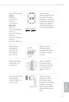
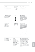
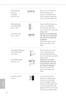
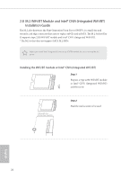
1 Thunderbolt AIC Connector (5-pin TB1) (see p.7, No. 24) Please connect a Thunderbolt™ add-in card (AIC) to this connector via the GPIO cable. *Please install the Thunderbolt™ AIC card to PCIE3 (default slot). RGB LED Headers (4-pin RGB_LED1) (see p.7, No. 6) (4-pin RGB_LED2) (see p.7, No. 26) B R G +12V 1 1 +12V G R B Addressable LED Headers (3-pin ADDR_LED1) (see p.7, No. 7) (3-pin ADDR_LED2) (see p.7, No. 27) GND DO_ADDR VOUT 1 1 GND DO_ADDR VOUT Post Status Checker (see p.1) DRAM CPU VGA BOOT 24 These two RGB LED headers are used to connect RGB LED extension cables which allow users to choose from various LED lighting effects. Caution: Never install the RGB LED cable in the wrong orientation; otherwise, the cable may be damaged. *Please refer to page 47 for for further instructions on this header. These two headers are used to connect Addressable LED extension cables which allow users to choose from various LED lighting effects. Caution: Never install the Addressable LED cable in the wrong orientation; otherwise, the cable may be damaged. *Please refer to page 48 for further instructions on this header. Post Status Checker (PSC) diagnoses the computer when users power on the machine. It emits a red light to indicate whether the CPU, memory, VGA or storage is dysfunctional. The lights go off if the four mentioned above are functioning normally. English
-
 1
1 -
2
-
3
-
4
-
5
-
6
-
7
-
8
-
9
-
10
-
11
-
12
-
13
-
14
-
15
-
16
-
17
-
18
-
19
-
20
-
21
-
22
-
23
-
24
-
25
-
 26
26 -
 27
27 -
 28
28 -
 29
29 -
 30
30 -
 31
31 -
 32
32 -
 33
33 -
 34
34 -
 35
35 -
 36
36 -
37
-
38
-
39
-
40
-
41
-
42
-
43
-
44
-
45
-
46
-
47
-
48
-
49
-
50
-
51
-
52
-
53
-
54
-
55
-
56
-
57
-
58
-
59
-
60
-
61
-
62
-
63
-
64
-
65
-
66
-
67
-
68
-
69
-
70
-
71
-
72
-
73
-
74
-
75
-
76
-
77
-
78
-
79
-
80
-
81
-
82
-
83
-
84
-
85
-
86
-
87
-
88
-
89
-
90
-
91
-
92
-
93
-
94
-
95
-
96
-
97
-
98
 |
 |
