ASRock B75TM-ITX User Manual - Page 23
Installing the CPU
 |
View all ASRock B75TM-ITX manuals
Add to My Manuals
Save this manual to your list of manuals |
Page 23 highlights
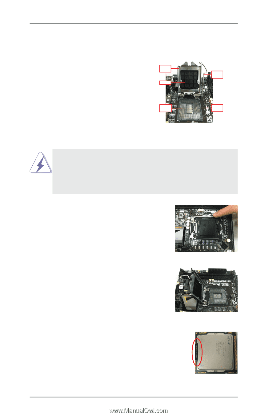
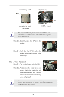
2.1 Installing the CPU In order to provide the LGA 1155 CPU sockets more protection and make the installation process easier, ASRock has added a new protection cover on top of the load plate to replace the former PnP caps that were under the load plate. For the installation of Intel® 1155-Pin CPUs with the new protection cover, please follow the steps below. Load Plate Cover Load Lever Contact Array Socket Body 1155-Pin Socket Overview Before you insert the 1155-Pin CPU into the socket, please check if the CPU surface is unclean or if there are any bent pins in the socket. Do not force to insert the CPU into the socket if above situation is found. Otherwise, the CPU will be seriously damaged. Step 1. Open the socket: Step 1-1.Disengage the lever by pressing it down and sliding it out of the hook. You do not have to remove the protection cover. Step 1-2.Keep the lever positioned at about 135 degrees in order to flip up the load plate. Step 2. Insert the 1155-Pin CPU: Step 2-1.Hold the CPU by the edge which is marked with a black line. Step 2-2.Orient the CPU with the Integrated Heat Sink up. Locate Pin1 and the two orientation key notches. 23 black line
-
 1
1 -
2
-
3
-
4
-
5
-
6
-
7
-
8
-
9
-
10
-
11
-
12
-
13
-
14
-
15
-
16
-
17
-
 18
18 -
 19
19 -
 20
20 -
 21
21 -
 22
22 -
 23
23 -
 24
24 -
 25
25 -
 26
26 -
 27
27 -
 28
28 -
29
-
30
-
31
-
32
-
33
-
34
-
35
-
36
-
37
-
38
-
39
-
40
-
41
-
42
-
43
-
44
-
45
-
46
-
47
-
48
-
49
-
50
-
51
-
52
-
53
-
54
-
55
-
56
-
57
-
58
-
59
-
60
-
61
-
62
-
63
-
64
-
65
-
66
-
67
 |
 |