ASRock B75TM-ITX User Manual - Page 31
Onboard Headers and Connectors
 |
View all ASRock B75TM-ITX manuals
Add to My Manuals
Save this manual to your list of manuals |
Page 31 highlights
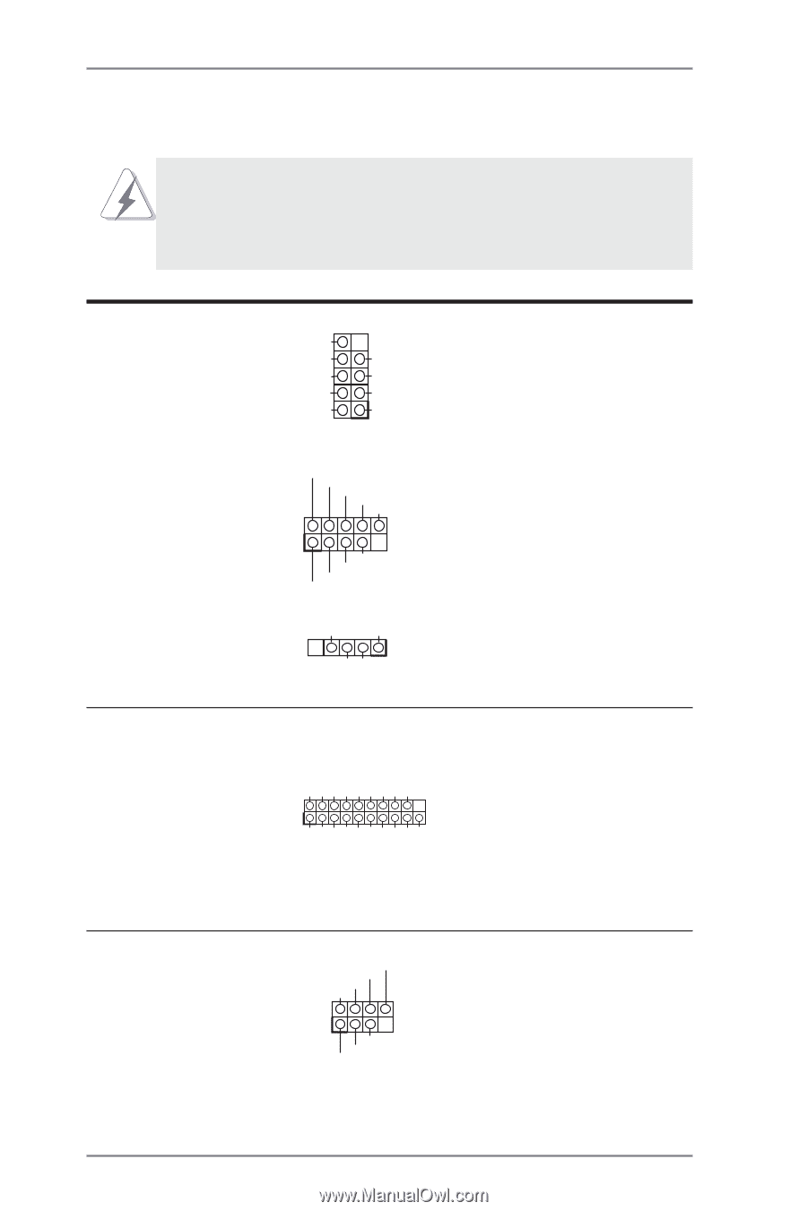
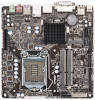
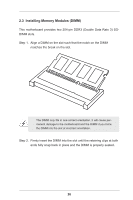
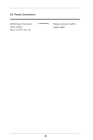
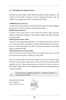
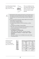
2.8 Onboard Headers and Connectors Onboard headers and connectors are NOT jumpers. Do NOT place jumper caps over these headers and connectors. Placing jumper caps over the headers and connectors will cause permanent damage to the motherboard! USB 2.0 Headers (9-pin USB4_5) (see p.13/15/17, No. 20) DUMMY GND +B -B USB_PWR GND +A -A USB_PWR 1 (9-pin USB6_7) (see p.13/15/17, No. 7) USB_PWR -B +B GND DUMMY 1 GND +A -A USB_PWR Besides two default USB 2.0 ports on the I/O panel, there are three USB 2.0 headers and one USB port on this motherboard. Each USB 2.0 header can support two USB 2.0 ports. (4-pin USB8) (see p.13/15/17, No. 3) GND +5VDC 1 +D -D IntA_PA_D+ IntA_PA_DGND IntA_PA_SSTX+ IntA_PA_SSTXGND IntA_PA_SSRX+ IntA_PA_SSRXVbus USB 3.0 Header (19-pin USB3_0_1) (see p.13/15/17, No. 9) 1 Dummy IntA_PB_D+ IntA_PB_D- GND IntA_PB_SSTX+ IntA_PB_SSTX- GND IntA_PB_SSRX+ IntA_PB_SSRX- Vbus Besides two default USB 3.0 ports on the I/O panel, there is one USB 3.0 header on this motherboard. The USB 3.0 header can support two USB 2.0 ports. Consumer Infrared Module Header (7-pin CIR1) (see p.13/15/17, No. 5) CIR input +5VA Learn-in LED 1 +5VA NC GND This header can be used to connect the remote controller receiver. 31
-
 1
1 -
2
-
3
-
4
-
5
-
6
-
7
-
8
-
9
-
10
-
11
-
12
-
13
-
14
-
15
-
16
-
17
-
18
-
19
-
20
-
21
-
22
-
23
-
24
-
25
-
 26
26 -
 27
27 -
 28
28 -
 29
29 -
 30
30 -
 31
31 -
 32
32 -
 33
33 -
 34
34 -
 35
35 -
 36
36 -
37
-
38
-
39
-
40
-
41
-
42
-
43
-
44
-
45
-
46
-
47
-
48
-
49
-
50
-
51
-
52
-
53
-
54
-
55
-
56
-
57
-
58
-
59
-
60
-
61
-
62
-
63
-
64
-
65
-
66
-
67
 |
 |