ASRock B760 Pro RS WiFi User Manual - Page 52
eDP Signal Connector
 |
View all ASRock B760 Pro RS WiFi manuals
Add to My Manuals
Save this manual to your list of manuals |
Page 52 highlights
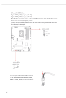
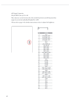
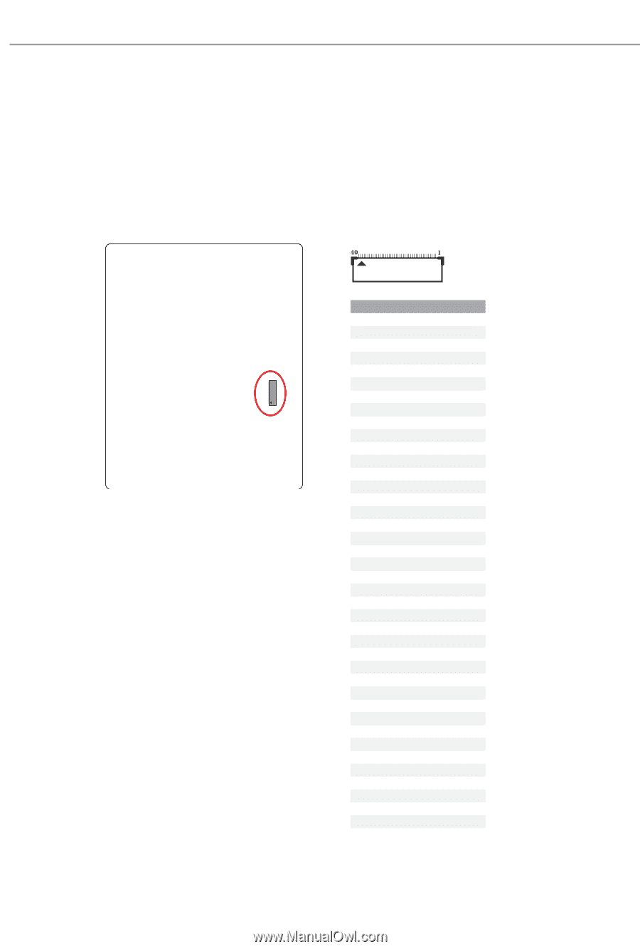
eDP Signal Connector (40-pin EDP1) (see p.8, No. 29) This connector on the bottom side of the motherboard is for an LCD monitor that supports an internal embedded DisplayPort (eDP). *Please refer to page 53 for further instructions on how to adjust the brightness. PIN SIGNAL 1 N/A 2 LCD_BLT_VCC 3 LCD_BLT_VCC 4 LCD_BLT_VCC 5 LCD_BLT_VCC 6 N/A 7 N/A 8 eDP_VARY_BL 9 eDP_BLON 10 BKT_GND 11 BKT_GND 12 BKT_GND 13 BKT_GND 14 eDP_HPD_CON 15 PNL_GND 16 PNL_GND 17 PNL_GND 18 PNL_GND 19 N/A 20 +LVDD 21 +LVDD 22 +LVDD 23 +LVDD 24 GND 25 eDP_AUX#_CON 26 eDP_AUX_CON 27 GND 28 eDP_TX0_CON 29 eDP_TX#0_CON 30 GND 31 eDP_TX1_CON 32 eDP_TX#1_CON 33 GND 34 N/A 35 N/A 36 GND 37 N/A 38 N/A 39 GND 40 N/A 48
-
 1
1 -
2
-
3
-
4
-
5
-
6
-
7
-
8
-
9
-
10
-
11
-
12
-
13
-
14
-
15
-
16
-
17
-
18
-
19
-
20
-
21
-
22
-
23
-
24
-
25
-
26
-
27
-
28
-
29
-
30
-
31
-
32
-
33
-
34
-
35
-
36
-
37
-
38
-
39
-
40
-
41
-
42
-
43
-
44
-
45
-
46
-
 47
47 -
 48
48 -
 49
49 -
 50
50 -
 51
51 -
 52
52 -
 53
53 -
 54
54 -
 55
55 -
 56
56 -
 57
57 -
58
-
59
-
60
-
61
-
62
-
63
-
64
-
65
-
66
-
67
-
68
-
69
 |
 |
48
eDP Signal Connector
(40-pin EDP1) (see p.8, No. 29)
°is connector on the bottom side of the motherboard is for an LCD monitor that
supports an internal embedded DisplayPort (eDP).
*Please refer to page
53
for further instructions on how to adjust the brightness.
PIN
SIGNAL
1
N/A
2
LCD_BLT_VCC
3
LCD_BLT_VCC
4
LCD_BLT_VCC
5
LCD_BLT_VCC
6
N/A
7
N/A
8
eDP_VARY_BL
9
eDP_BLON
10
BKT_GND
11
BKT_GND
12
BKT_GND
13
BKT_GND
14
eDP_HPD_CON
15
PNL_GND
16
PNL_GND
17
PNL_GND
18
PNL_GND
19
N/A
20
+LVDD
21
+LVDD
22
+LVDD
23
+LVDD
24
GND
25
eDP_AUX#_CON
26
eDP_AUX_CON
27
GND
28
eDP_TX0_CON
29
eDP_TX#0_CON
30
GND
31
eDP_TX1_CON
32
eDP_TX#1_CON
33
GND
34
N/A
35
N/A
36
GND
37
N/A
38
N/A
39
GND
40
N/A