ASRock B85M BTC User Manual - Page 24
Jumpers Setup, Clear CMOS, Default
 |
View all ASRock B85M BTC manuals
Add to My Manuals
Save this manual to your list of manuals |
Page 24 highlights
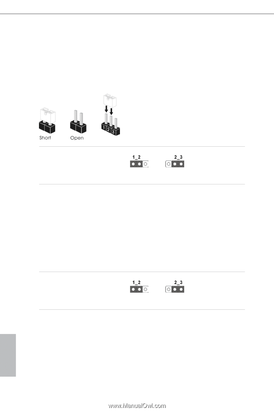
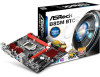
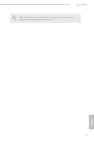
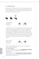
2.5 Jumpers Setup The illustration shows how jumpers are setup. When the jumper cap is placed on the pins, the jumper is "Short". If no jumper cap is placed on the pins, the jumper is "Open". The illustration shows a 3-pin jumper whose pin1 and pin2 are "Short" when a jumper cap is placed on these 2 pins. Clear CMOS Jumper (CLRCMOS1) (see p.9, No. 18) Default Clear CMOS CLRCMOS1 allows you to clear the data in CMOS. To clear and reset the system parameters to default setup, please turn off the computer and unplug the power cord from the power supply. After waiting for 15 seconds, use a jumper cap to short pin2 and pin3 on CLRCMOS1 for 5 seconds. However, please do not clear the CMOS right after you update the BIOS. If you need to clear the CMOS when you just finish updating the BIOS, you must boot up the system first, and then shut it down before you do the clear-CMOS action. Please be noted that the password, date, time, and user default profile will be cleared only if the CMOS battery is removed. USB Power Jumper (USB01_PWR1) (see p.9, No. 1) +5V (Default) +5VSB USB Power Jumper is specifically designed for users who use LED keyboard / mouse. (only for the USB01 ports) Pin 1-2 shorted (default): Stable voltage and high current is provided for L��E�D���k��e��y��b���o��a��r��d m���o���u��s��e T��h�e��b�a�c�k�light of your keyboard / mouse will be OFF when the PC is off. Pin 2-3 shorted: +5VSB voltage is provided for L��E�D���k��e��y��b���o��a��r��d m����o��u��s��e E���n��a��b���l�e���t�h���e���w���a�k�e�-�u�p��fu��n�c�tion of your keyboard / mouse. The backlight of your keyboard / mouse will be ON when the PC is in standby mode. 20 English
-
 1
1 -
2
-
3
-
4
-
5
-
6
-
7
-
8
-
9
-
10
-
11
-
12
-
13
-
14
-
15
-
16
-
17
-
18
-
 19
19 -
 20
20 -
 21
21 -
 22
22 -
 23
23 -
 24
24 -
 25
25 -
 26
26 -
 27
27 -
 28
28 -
 29
29 -
30
-
31
-
32
-
33
-
34
-
35
-
36
-
37
-
38
-
39
-
40
-
41
-
42
-
43
-
44
-
45
-
46
-
47
-
48
-
49
-
50
-
51
-
52
-
53
-
54
-
55
-
56
-
57
-
58
-
59
-
60
-
61
-
62
-
63
-
64
-
65
-
66
-
67
-
68
-
69
-
70
-
71
-
72
-
73
-
74
-
75
-
76
-
77
-
78
-
79
-
80
-
81
 |
 |