ASRock ConRoe1333-eSATA2 User Manual - Page 28
con nect HDMI Digital TV
 |
View all ASRock ConRoe1333-eSATA2 manuals
Add to My Manuals
Save this manual to your list of manuals |
Page 28 highlights
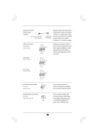
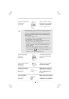
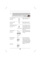
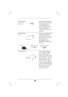
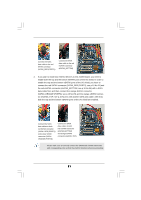
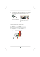
HDMI_SPDIF Header (3-pin HDMI_SPDIF1) (see p.10 No. 30) 1 GND SPDIFOUT +5V HDMI_SPDIF Cable (Optional) C B A HDMI_SPDIF header, providing SPDIF audio output to HDMI VGA card, allows the system to con nect HDMI Digital TV/ projector/LCD devices. Please connect the HDMI_SPDIF connector of HDMI VGA card to this header. Please connect the black end (A) of HDMI_SPDIF cable to the HDMI_SPDIF header on the motherboard. Then connect the white end (B or C) of HDMI_SPDIF cable to the HDMI_SPDIF connector of HDMI VGA card. A. black end +5V SPDIFOUT GND blue black USB+1394 Bracket B. white end (2-pin) SPDIFOUT GND blue black C. white end (3-pin) SPDIFOUT GND blue black This USB+1394 bracket can support 2 additional USB 2.0 ports and 1 IEEE 1394 port. Please connect the blue connector on the cable of this USB+1394 bracket to the USB 2.0 header (USB23, USB45, or USB67), and connect the red connector on the cable of this USB+1394 bracket to the IEEE 1394 header (BACK_1394). Then fasten the USB+1394 bracket to the chassis with screws. 28
-
 1
1 -
2
-
3
-
4
-
5
-
6
-
7
-
8
-
9
-
10
-
11
-
12
-
13
-
14
-
15
-
16
-
17
-
18
-
19
-
20
-
21
-
22
-
 23
23 -
 24
24 -
 25
25 -
 26
26 -
 27
27 -
 28
28 -
 29
29 -
 30
30 -
 31
31 -
 32
32 -
 33
33 -
34
-
35
-
36
-
37
-
38
-
39
-
40
-
41
-
42
-
43
-
44
-
45
-
46
-
47
-
48
-
49
-
50
-
51
-
52
-
53
-
54
-
55
-
56
-
57
-
58
-
59
-
60
-
61
 |
 |
