ASRock Fatal1ty FM2A88X Killer User Manual - Page 31
PLED System Power LED, HDLED Hard Drive Activity LED, Chassis and Power Fan
 |
View all ASRock Fatal1ty FM2A88X Killer manuals
Add to My Manuals
Save this manual to your list of manuals |
Page 31 highlights
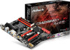
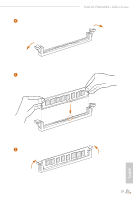
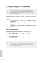
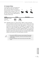
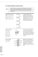
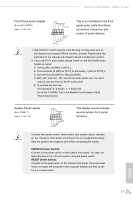
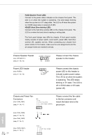
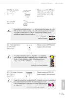
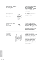
PLED (System Power LED): Connect to the power status indicator on the chassis front panel. The LED is on when the system is operating. The LED keeps blinking when the sys-tem is in S1 sleep state. The LED is off when the system is in S3/S4 sleep state or powered off (S5). HDLED (Hard Drive Activity LED): Connect to the hard drive activity LED on the chassis front panel. The LED is on when the hard drive is reading or writing data. The front panel design may differ by chassis. A front panel module mainly consists of power switch, reset switch, power LED, hard drive activity LED, speaker and etc. When connecting your chassis front panel module to this header, make sure the wire assignments and the pin assign-ments are matched correctly. Chassis Speaker Header (4-pin SPEAKER 1) (see p.11 No. 16) DUMMY SPEAKER 1 +5V DUMMY Please connect the chassis speaker to this header. Power LED Header (3-pin PLED1) (see p.11 No. 18 1 PLED- PLED+ PLED+ Please connect the chassis power LED to this header to indicate system power status. The LED is on when the system is operating. The LED keeps blinking in S1 state. The LED is off in S3/S4 state or S5 state (power off). Chassis and Power Fan Connectors GND +12V (4-pin CHA_FAN1) CHA_FAN_SPEED (see p.11 No. 17) FAN_SPEED_CONTROL Please connect the fan cable to the fan connector and match the black wire to the ground pin. English (4-pin CHA_FAN2) (see p.11 No. 15) (4-pin CHA_FAN3) (see p.11 No. 9) (3-pin PWR_FAN1) (see p.11 No. 2) 24
-
 1
1 -
2
-
3
-
4
-
5
-
6
-
7
-
8
-
9
-
10
-
11
-
12
-
13
-
14
-
15
-
16
-
17
-
18
-
19
-
20
-
21
-
22
-
23
-
24
-
25
-
 26
26 -
 27
27 -
 28
28 -
 29
29 -
 30
30 -
 31
31 -
 32
32 -
 33
33 -
 34
34 -
 35
35 -
 36
36 -
37
-
38
-
39
-
40
-
41
-
42
-
43
-
44
-
45
-
46
-
47
-
48
-
49
-
50
-
51
-
52
-
53
-
54
-
55
-
56
-
57
-
58
-
59
-
60
-
61
-
62
-
63
-
64
-
65
-
66
-
67
-
68
-
69
-
70
-
71
-
72
-
73
-
74
-
75
-
76
-
77
 |
 |