ASRock Fatal1ty FM2A88X Killer User Manual - Page 33
SLI/XFIRE Power Connector, Chassis Intrusion Header
 |
View all ASRock Fatal1ty FM2A88X Killer manuals
Add to My Manuals
Save this manual to your list of manuals |
Page 33 highlights
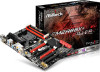
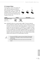
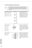
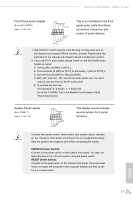
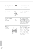
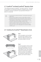
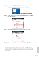
SLI/XFIRE Power Connector (4-pin SLI/XFIRE_PWR1) (see p.11, No. 24) Serial port Header (9-pin COM1) (see p.11 No. 25) RRXD1 DDTR#1 DDSR#1 CCTS#1 1 RRI#1 RRTS#1 GND TTXD1 DDCD#1 Please connect this connector with a hard disk power connector when two graphics cards are installed on this motherboard. This COM1 header supports a serial port module. Chassis Intrusion Header (2-pin CI1) (see p.11, No. 19) 1 GND Signal This motherboard supports CASE OPEN detection feature that detects if the chassis cover has been removed. This feature requires a chassis with chassis intrusion detection design. TPM Header (17-pin TPMS1) (see p.11, No. 23) 1 GND +3VSB LAD0_L +3V LAD3_L TPM_RST# LFRAME#_L CK_33M_TPM F_CLKRUN# SERIRQ# S_PWRDWN# GND LAD1_L LAD2_L SMB_DATA_MAIN SMB_CLK_MAIN GND This connector supports Trusted Platform Module (TPM) system, which can securely store keys, digital certificates, passwords, and data. A TPM system also helps enhance network security, protects digital identities, and ensures platform integrity. English 26
-
 1
1 -
2
-
3
-
4
-
5
-
6
-
7
-
8
-
9
-
10
-
11
-
12
-
13
-
14
-
15
-
16
-
17
-
18
-
19
-
20
-
21
-
22
-
23
-
24
-
25
-
26
-
27
-
 28
28 -
 29
29 -
 30
30 -
 31
31 -
 32
32 -
 33
33 -
 34
34 -
 35
35 -
 36
36 -
 37
37 -
 38
38 -
39
-
40
-
41
-
42
-
43
-
44
-
45
-
46
-
47
-
48
-
49
-
50
-
51
-
52
-
53
-
54
-
55
-
56
-
57
-
58
-
59
-
60
-
61
-
62
-
63
-
64
-
65
-
66
-
67
-
68
-
69
-
70
-
71
-
72
-
73
-
74
-
75
-
76
-
77
 |
 |