ASRock Fatal1ty P67 Professional Quick Installation Guide - Page 34
Serial ATA SATA
 |
View all ASRock Fatal1ty P67 Professional manuals
Add to My Manuals
Save this manual to your list of manuals |
Page 34 highlights
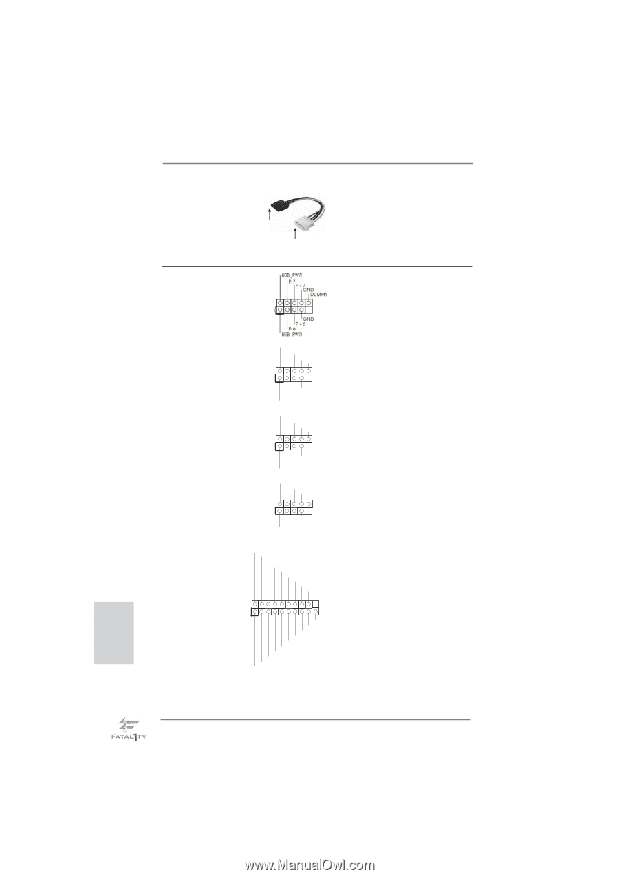
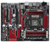
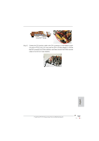
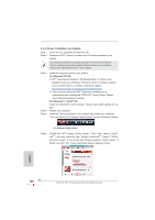
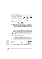
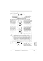
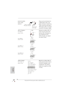
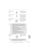
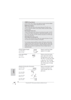
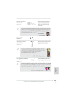
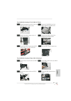
Serial ATA (SATA) Power Cable (Optional) connect to the SATA HDD power connector connect to the power supply USB 2.0 Headers (9-pin USB6_7) (see p.4 No. 35) (9-pin USB8_9) (see p.4 No. 34) (9-pin USB10_11) (see p.4 No. 33) (9-pin USB12_13) (see p.4 No. 32) USB 3.0 Header (19-pin USB3_2_3) (see p.4 No. 36) USB_PWR P-9 P+9 GND DUMMY 1 GND P+8 P-8 USB_PWR USB_PWR P-11 P+11 GND DUMMY 1 GND P+10 P-10 USB_PWR USB_PWR P-13 P+13 GND DUMMY 1 GND P+12 P-12 USB_PWR IntA_P2_D+ IntA_P2_DGND IntA_P2_SSTX+ IntA_P2_SSTXGND IntA_P2_SSRX+ IntA_P2_SSRXVbus 1 Vbus IntA_P1_SSRXIntA_P1_SSRX+ GND IntA_P1_SSTXIntA_P1_SSTX+ GND IntA_P1_DIntA_P1_D+ ID Please connect the black end of SATA power cable to the power connector on each drive. Then connect the white end of SATA power cable to the power connector of the power supply. Besides four default USB 2.0 ports on the I/O panel, there are four USB 2.0 headers on this motherboard. Each USB 2.0 header can support two USB 2.0 ports. Besides four default USB 3.0 ports on the I/O panel, there is one USB 3.0 header on this motherboard. This USB 3.0 header can support two USB 3.0 ports. English 34 Fatal1ty P67 Professional Series Motherboard
-
 1
1 -
2
-
3
-
4
-
5
-
6
-
7
-
8
-
9
-
10
-
11
-
12
-
13
-
14
-
15
-
16
-
17
-
18
-
19
-
20
-
21
-
22
-
23
-
24
-
25
-
26
-
27
-
28
-
 29
29 -
 30
30 -
 31
31 -
 32
32 -
 33
33 -
 34
34 -
 35
35 -
 36
36 -
 37
37 -
 38
38 -
 39
39 -
40
-
41
-
42
-
43
-
44
-
45
-
46
-
47
-
48
-
49
-
50
-
51
-
52
-
53
-
54
-
55
-
56
-
57
-
58
-
59
-
60
-
61
-
62
-
63
-
64
-
65
-
66
-
67
-
68
-
69
-
70
-
71
-
72
-
73
-
74
-
75
-
76
-
77
-
78
-
79
-
80
-
81
-
82
-
83
-
84
-
85
-
86
-
87
-
88
-
89
-
90
-
91
-
92
-
93
-
94
-
95
-
96
-
97
-
98
-
99
-
100
-
101
-
102
-
103
-
104
-
105
-
106
-
107
-
108
-
109
-
110
-
111
-
112
-
113
-
114
-
115
-
116
-
117
-
118
-
119
-
120
-
121
-
122
-
123
-
124
-
125
-
126
-
127
-
128
-
129
-
130
-
131
-
132
-
133
-
134
-
135
-
136
-
137
-
138
-
139
-
140
-
141
-
142
-
143
-
144
-
145
-
146
-
147
-
148
-
149
-
150
-
151
-
152
-
153
-
154
-
155
-
156
-
157
-
158
-
159
-
160
-
161
-
162
-
163
-
164
-
165
-
166
-
167
-
168
-
169
-
170
-
171
-
172
-
173
-
174
-
175
-
176
-
177
-
178
-
179
-
180
-
181
-
182
-
183
-
184
-
185
-
186
-
187
-
188
-
189
-
190
-
191
-
192
-
193
-
194
-
195
-
196
-
197
-
198
-
199
-
200
-
201
-
202
-
203
-
204
-
205
-
206
-
207
-
208
-
209
-
210
-
211
-
212
-
213
-
214
-
215
-
216
-
217
-
218
-
219
-
220
-
221
-
222
-
223
-
224
-
225
-
226
-
227
-
228
-
229
-
230
-
231
-
232
-
233
-
234
-
235
-
236
-
237
-
238
-
239
-
240
-
241
-
242
-
243
-
244
-
245
-
246
-
247
-
248
-
249
-
250
-
251
-
252
-
253
-
254
-
255
-
256
-
257
-
258
-
259
-
260
-
261
-
262
-
263
-
264
-
265
-
266
-
267
-
268
-
269
-
270
-
271
-
272
-
273
-
274
-
275
-
276
-
277
-
278
-
279
-
280
-
281
-
282
-
283
-
284
-
285
-
286
-
287
-
288
-
289
-
290
-
291
-
292
-
293
-
294
-
295
-
296
-
297
-
298
-
299
-
300
-
301
-
302
-
303
-
304
-
305
-
306
-
307
-
308
-
309
-
310
-
311
-
312
-
313
-
314
 |
 |