ASRock G41MH/USB3 User Manual
ASRock G41MH/USB3 Manual
 |
View all ASRock G41MH/USB3 manuals
Add to My Manuals
Save this manual to your list of manuals |
ASRock G41MH/USB3 manual content summary:
- ASRock G41MH/USB3 | User Manual - Page 1
G41MH/USB3 User Manual Version 1.0 Published May 2010 Copyright©2010 ASRock INC. All rights reserved. 1 - ASRock G41MH/USB3 | User Manual - Page 2
purchaser for backup purpose, without written consent of ASRock Inc. Products and corporate names appearing in this manual may or may not be registered trademarks or copyrights USA ONLY The Lithium battery adopted on this motherboard contains Perchlorate, a toxic substance controlled in Perchlorate - ASRock G41MH/USB3 | User Manual - Page 3
and Connectors 23 2.10 SATAII Hard Disk Setup Guide 27 2.11 Serial ATA (SATA) / Serial ATAII (SATAII) Hard Disks Installation 28 2.12 Driver Installation Guide 28 2.13 Untied Overclocking Technology 28 3 BIOS SETUP UTILITY 29 3.1 Introduction 29 3.1.1 BIOS Menu Bar 29 3.1.2 Navigation - ASRock G41MH/USB3 | User Manual - Page 4
3.7 Security Screen 52 3.8 Exit Screen 53 4 Software Support 54 4.1 Install Operating System 54 4.2 Support CD Information 54 4.2.1 Running Support CD 54 4.2.2 Drivers Menu 54 4.2.3 Utilities Menu 54 4.2.4 Contact Information 54 4 - ASRock G41MH/USB3 | User Manual - Page 5
guide to BIOS setup and information of the Support CD. Because the motherboard specifications and the BIOS software might be updated, the content of this manual will be subject to change without notice. In case any modifications of this manual occur, the updated version will be available on ASRock - ASRock G41MH/USB3 | User Manual - Page 6
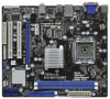
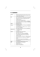
Core / Celeron®, supporting Penryn Quad Core Yorkfield and Dual Core Wolfdale processors - Supports FSB1333/1066/800/533 MHz - Supports Hyper-Threading Technology (see CAUTION 1) - Supports Untied Overclocking Technology (see CAUTION 2) - Supports EM64T CPU - Northbridge: Intel® G41 - Southbridge - ASRock G41MH/USB3 | User Manual - Page 7
(support 4 USB 2.0 ports) - 8Mb AMI BIOS - AMI Legal BIOS - Supports "Plug and Play" - ACPI 1.1 Compliance Wake Up Events - Supports jumperfree - AMBIOS 2.3.1 Support - Supports I. O. T. (Intelligent Overclocking Technology) - Drivers, Utilities, AntiVirus Software (Trial Version), ASRock Software - ASRock G41MH/USB3 | User Manual - Page 8
corresponding memory support frequency. CPU FSB Frequency Memory Support Frequency 1333 DDR3 800, DDR3 1066, DDR3 1333 1066 DDR3 800, DDR3 1066 800 DDR3 800 533 DDR3 800 * DDR3 1333 memory modules will operate in overclocking mode. * When you use a FSB533-CPU on this motherboard, it will - ASRock G41MH/USB3 | User Manual - Page 9
of Intelligent Energy Saver. ASRock website: http://www.asrock.com 10. ASRock Instant Flash is a BIOS flash utility embedded in Flash ROM. This convenient BIOS update tool allows you to update system BIOS without entering operating systems first like MS-DOS or Windows®. With this utility, you - ASRock G41MH/USB3 | User Manual - Page 10
the completed system shall be under 1.00W in off mode condition. To meet EuP standard, an EuP ready motherboard and an EuP ready power supply are required. According to Intel's suggestion, the EuP ready power supply must recommend you checking with the power supply manufacturer for more details. 10 - ASRock G41MH/USB3 | User Manual - Page 11
bit, 240-pin module) DDR3_A1 (64 bit, 240-pin module) HDMI1 32 USB 2.0 T: USB0 B: USB1 Top: RJ-45 PWR_FAN1 31 7 24.4cm (9.6 in) G41MH/USB3 1 Designed in Taipei ErP/EuP Ready USB 2.0: USB2 USB 3.0: USB3 LAN PHY 30 Intel G41 Chipset CHA_FAN1 8 TPM1 1 29 28 27 26 Top: LINE IN Center - ASRock G41MH/USB3 | User Manual - Page 12
10 11 12 USB 2.0 Port (USB2) USB 3.0 Port (USB3) USB 2.0 Ports (USB01) HDMI Port VGA/DVI-D Port PS/2 Keyboard Port (Purple) * There are two LED next to the LAN Multi-Streaming. For Windows® XP: After USB Keyboard and Mouse on USB 3.0 port. Besides, USB 3.0 port does not support Wake Up function. - ASRock G41MH/USB3 | User Manual - Page 13
Precautions Take note of the following precautions before you install motherboard components or change any motherboard settings. 1. Unplug the power cord from the wall socket before touching any component. 2. To avoid damaging the motherboard components due to static electricity, NEVER place your - ASRock G41MH/USB3 | User Manual - Page 14
the installation of Intel 775-LAND CPU, please follow the steps below. 775-Pin Socket Overview Before you insert the 775-LAND CPU into the socket, please check if the CPU surface is unclean or if there is any bent pin on the socket. Do not force to insert the CPU into the socket if above situation - ASRock G41MH/USB3 | User Manual - Page 15
to use the cap tab to handle and avoid kicking off the PnP cap. 2. This cap must be placed if returning the motherboard for after service. Step 4. Close the socket: Step 4-1. Rotate the load plate onto the IHS. Step 4-2. While pressing down lightly on load plate, engage the load lever. Step - ASRock G41MH/USB3 | User Manual - Page 16
Heatsink This motherboard is equipped with 775-Pin socket that supports Intel 775-LAND CPU. Please adopt the type of heatsink and cooling fan compliant with Intel 775-LAND CPU to dissipate heat. Before you installed the heatsink, you need to spray thermal interface material between the CPU and the - ASRock G41MH/USB3 | User Manual - Page 17
2.5 Installation of Memory Modules (DIMM) G41MH/USB3 motherboard provides two 240-pin DDR3 (Double Data Rate 3) DIMM slots, and supports Dual Channel Memory Technology. For dual channel configuration, you always need to install two identical (the same brand, speed, size and chip-type) memory modules - ASRock G41MH/USB3 | User Manual - Page 18
(PCI and PCI Express Slots) There are 2 PCI slots and 2 PCI Express slots on this motherboard. PCI slots: PCI slots are used to install expansion cards that have the 32-bit PCI interface. PCIE slots: PCIE1 (PCIE x1 slot) is used for PCI Express cards with x1 lane width cards, such as Gigabit LAN - ASRock G41MH/USB3 | User Manual - Page 19
of dual monitor feature without installing any add-on VGA card to this motherboard. This motherboard also provides independent display controllers for DVI-D, D-Sub and HDMI to support dual VGA output so that DVI-D, D-sub and HDMI can drive same or different display contents. To enable dual monitor - ASRock G41MH/USB3 | User Manual - Page 20
Click "Apply" or "OK" to apply these new values. G. Repeat steps C through E for the diaplay icon identified by the number one and two. For Windows® 7 / 7 64-bit / VistaTM / VistaTM 64-bit OS: Right click the desktop, choose "Personalize", and select the "Display Settings" tab so that you can adjust - ASRock G41MH/USB3 | User Manual - Page 21
function is supported on this motherboard. To use HDCP function with this motherboard, you need to adopt the monitor that supports HDCP function as well. Therefore, you can enjoy the superior display quality with high-definition HDCP encryption contents. Please refer to below instruction for more - ASRock G41MH/USB3 | User Manual - Page 22
wake +5V +5V_DUAL up events. Note: To select +5V_DUAL, it requires 2 Amp and higher standby current provided by power supply. When you select +5V_DUAL, USB devices can wake up the system under S3 (Suspend to RAM) state. USB_PWR3 1_2 (see p.11, No. 19) 2_3 Short pin2, pin3 to enable +5VSB - ASRock G41MH/USB3 | User Manual - Page 23
(Blue) (39-pin IDE1, see p.11 No. 9) PIN1 IDE1 connect the blue end to the motherboard connect the black end to the IDE devices 80-conductor ATA 66/100 cable Note: Please refer to the instruction of your IDE device vendor for the details. Serial ATAII Connectors (SATAII_1: see p.11, No. 16 - ASRock G41MH/USB3 | User Manual - Page 24
GND P+4 P-4 USB_PWR IRTX +5V DUMMY 1 GND IRRX Besides three default USB 2.0 ports on the I/O panel, there are two USB 2.0 headers on this motherboard. Each USB 2.0 header can support two USB 2.0 ports. This header supports an optional wireless transmitting and receiving infrared module. Print Port - ASRock G41MH/USB3 | User Manual - Page 25
supports Jack Sensing, but the panel wire on the chassis must support HDA to function correctly. Please follow the instruction in our manual and chassis manual CPU Fan Connector FAN_SPEED_CONTROL 4 (4-pin CPU_FAN1) CPU_FAN_SPEED 3 +12V 2 (see p.11 No. 33) GND 1 Please connect a CPU fan - ASRock G41MH/USB3 | User Manual - Page 26
Though this motherboard provides 4-Pin CPU fan (Quiet Fan) support, the 3-Pin CPU fan still can work successfully even without the fan speed control function. If you plan to connect the 3-Pin CPU fan to the CPU fan connector on this motherboard, please connect it to Pin 1-3. Pin 1-3 Connected 3-Pin - ASRock G41MH/USB3 | User Manual - Page 27
guide. Some default setting of SATAII hard disks may not be at SATAII mode, which operate with the best performance. In order to enable SATAII function, please follow the below instruction 's website for details: http://www.hitachigst.com/hdd/support/download.htm The above examples are just for your - ASRock G41MH/USB3 | User Manual - Page 28
Technology This motherboard supports Untied Overclocking Technology, which means during overclocking, FSB enjoys better margin due to fixed PCI / PCIE buses. Before you enable Untied Overclocking function, please enter "Overclock Mode" option of BIOS setup to set the selection from [Auto] to [Manual - ASRock G41MH/USB3 | User Manual - Page 29
motherboard stores the BIOS SETUP UTILITY. You may run the BIOS SETUP UTILITY when you start up the computer. Please press or during the Power-On-Self-Test (POST) to enter the BIOS on. Because the BIOS software is constantly being updated, the following BIOS setup screens and descriptions - ASRock G41MH/USB3 | User Manual - Page 30
System Overview System Time System Date [14:00:09] [Thu 05/13/2010] BIOS Version : G41MH/USB3 P1.00 Processor Type : Intel (R) Pentium (R) Dual CPU E2220 @ 2.40GHz (64bit) Processor Speed : 2400MHz Microcode Update : 6FB/A3 Cache Size : 1024KB Total Memory DDR3_A1 DDR3_A2 : 1024MB Single - ASRock G41MH/USB3 | User Manual - Page 31
Load CPU EZ OC Setting You can use this option to load CPU EZ overclocking setting. Please note that overclocing may cause damage to your CPU and motherboard. It CPU and memory module you adopt on this motherboard. Please refer to page 8 for the CPU FSB frequency and its corresponding memory support - ASRock G41MH/USB3 | User Manual - Page 32
Timing Configuration BIOS SETUP UTILITY OC Tweaker DRAM Timing Control DRAM tCL 6 DRAM tRCD 6 DRAM tRP 6 DRAM tRAS 15 DRAM tRFC 44 DRAM tWR 6 DRAM tWTR 4 DRAM tRRD 3 DRAM tRTP 4 [Auto] [Auto] [Auto] [Auto] [Auto] [Auto] [Auto] [Auto] [Auto] DRAM tCL Value Min = 5 Max = 10 +F1 - ASRock G41MH/USB3 | User Manual - Page 33
of this motherboard. If the CPU you adopt supports EIST (Intel Disabled]. If you install Windows® XP and select Overclock Mode Use this to select Overclock Mode. Configuration options: [Auto], [Manual], [I.O.T.] and [Optimized]. The default value is [Auto]. If you select [Manual], Untied Overclocking - ASRock G41MH/USB3 | User Manual - Page 34
DRAM Voltage Use this to select DRAM Voltage. Configuration options: [Auto], [1.300V] to [2.050V]. The default value of this feature is [Auto]. NB Voltage Use this to select NB Voltage. Configuration options: [Auto], [1.046V] to [1.493V]. The default value of this feature is [Auto]. SB Voltage Use - ASRock G41MH/USB3 | User Manual - Page 35
in below sections may cause system to malfunction. CPU Configuration Chipset Configuration ACPI Configuration Storage Configuration PCIPnP Configuration Floppy Configuration SuperIO Configuration USB Configuration BIOS Update Utility ASRock Instant Flash Select Screen Select Item Enter Go to - ASRock G41MH/USB3 | User Manual - Page 36
"Unlocked", you will find an item Ratio CMOS Setting appears to allow you changing the ratio value of this motherboard. Ratio CMOS Setting If the ratio status is unlocked, you will find this item appear to allow you changing the ratio value of this motherboard. If the CPU you adopt supports 36 - ASRock G41MH/USB3 | User Manual - Page 37
optimization for this technology, such as Microsoft® Windows® XP / VistaTM / 7. Set to [Enabled] if using Microsoft® Windows® XP, VistaTM, 7 or Linux kernel version 2.4.18 or higher. This option will be hidden if the installed CPU does not support Hyper-Threading technology. Intel (R) SpeedStep(tm - ASRock G41MH/USB3 | User Manual - Page 38
Energy Saver Primary Graphics Adapter Shared Memory PAVP Mode DVMT Mode Select DVMT/FIXED Memory [Disabled] [PCI] [Auto] [Disabled] [DVMT Mode] [Maximum DVMT] Onboard HD Audio Front Panel OnBoard Lan [Auto] [Auto] [Enabled] +F1 F9 F10 ESC Select Screen Select Item Change Option General Help - ASRock G41MH/USB3 | User Manual - Page 39
DRAM CH0 G3 (Control2) This controls the number of DRAM CH0 G3 (Control2). Min: 1. Max: 15. The default value is [Auto]. DRAM CH0 G4 (Clocks1) This controls the number of DRAM CH0 G4 (Clocks1). Min: 1. Max: 15. The default value is [Auto]. DRAM CH0 G5 (Clocks2) This controls the number of DRAM CH0 - ASRock G41MH/USB3 | User Manual - Page 40
DRAM DLL SKEW Configuration BIOS SETUP UTILITY Advanced DRAM DLL SKEW Settings DRAM CH0 CLKSET0 SKEW Info:0-0-0-0-0-0 DRAM CH0 CLKSET0 SKEW [Auto] DRAM CH0 CLKSET1 SKEW Info:0-0-0-0-0-0 DRAM CH0 CLKSET1 - ASRock G41MH/USB3 | User Manual - Page 41
set this item to [Enabled]. Besides the BIOS option, you can also choose our Intelligent Energy [PCI] or [PCI Express] as the boot graphic adapter priority. The default value is [PCI]. Intel® 4 Series Express chipset family to support increased content protection and robustness requirements for - ASRock G41MH/USB3 | User Manual - Page 42
motherboard through efficient memory utilization. In DVMT mode, the graphics driver not be used under Windows® VistaTM OS because the driver will intelligently detect physical onboard HD Audio will be disabled when PCI Sound Card is plugged. Front Panel Select [Auto] or [Disabled] - ASRock G41MH/USB3 | User Manual - Page 43
ACPI Configuration BIOS SETUP UTILITY Advanced ACPI Configuration Suspend To RAM Restore on AC/Power Loss Ring-In Power On PCI Devices Select [Auto] will enable this feature if the OS supports it. Check Ready Bit Use this item to enable or motherboard to submit Windows® VistaTM certification. 43 - ASRock G41MH/USB3 | User Manual - Page 44
3.4.4 Storage Configuration BIOS SETUP UTILITY Advanced Storage Configuration ATA/IDE Configuration SATAII will not work, only IDE will work. Because Intel® ICH7 south bridge only supports four IDE devices under legacy OS (Windows NT), you have to choose [SATA 1, SATA 2, SATA 3, SATA 4], [SATA - ASRock G41MH/USB3 | User Manual - Page 45
as the example in the following instruction. BIOS SETUP UTILITY Advanced Primary IDE Master :ST340014A :40.0 GB :Supported :16Sectors :4 :MultiWord DMA-2 :Ultra DMA-5 :Supported [Auto] [Auto] [Auto for a hard disk > 512 MB under DOS and Windows; for Netware and UNIX user, select [Disabled] to - ASRock G41MH/USB3 | User Manual - Page 46
to maximize the IDE hard disk data transfer rate. 3.4.5 PCIPnP Configuration BIOS SETUP UTILITY Advanced Advanced PCI / PnP Settings PCI Latency Timer PCI IDE BusMaster [32] [Enabled] Value in units of PCI clocks for PCI device latency timer register. +F1 F9 F10 ESC Select Screen Select Item - ASRock G41MH/USB3 | User Manual - Page 47
Address Parallel Port Mode EPP Version ECP Mode DMA Channel Parallel Port IRQ [Enabled] [3F8 / IRQ4] [Disabled] [378] [ECP + EPP] [1.9] [DMA3] [IRQ7] Allow BIOS to Enable or Disable Floppy Controller. +F1 F9 F10 ESC Select Screen Select Item Change Option General Help Load Defaults Save and Exit - ASRock G41MH/USB3 | User Manual - Page 48
Parallel Port Address Use this item to set the address for the onboard parallel port or disable it. Configuration options: [Disabled], [378], and [278]. Parallel Port Mode Use this item to set the operation mode of the parallel port. The default value is [ECP+EPP]. If this option is set to [ECP+EPP - ASRock G41MH/USB3 | User Manual - Page 49
issue, it is recommended to select [Disabled] to enter OS. [BIOS Setup Only] - USB devices are allowed to use only under BIOS setup and Windows / Linux OS. USB 3.0 Controller Use this item to enable or disable the use of USB 3.0 controller. USB Keyboard/Remote Power On Use this item to enable or - ASRock G41MH/USB3 | User Manual - Page 50
to monitor the status of the hardware on your system, including the parameters of the CPU temperature, motherboard temperature, CPU fan speed, chassis fan speed, and the critical voltage. BIOS SETUP UTILITY Main OC Tweaker Advanced H/W Monitor Boot Security Exit Hardware Health Event Monitoring - ASRock G41MH/USB3 | User Manual - Page 51
to configure the boot settings and the boot priority. BIOS SETUP UTILITY Main OC Tweaker Advanced H/W Monitor Boot Full Screen Logo AddOn ROM Display Boot Logo Boot From Onboard LAN Bootup Num-Lock [Enabled] [Enabled] [Auto] [Disabled] Scenery] and [ASRock]. The default value is [Auto]. 51 - ASRock G41MH/USB3 | User Manual - Page 52
this item to enable or disable the Boot From Onboard LAN feature. Boot Up Num-Lock If this item is set /user password for the system. For the user password, you may also clear it. BIOS SETUP UTILITY Main OC Tweaker Advanced H/W Monitor Boot Security Exit Security Settings Supervisor Password : - ASRock G41MH/USB3 | User Manual - Page 53
. Discard Changes When you select this option, it will pop-out the following message, "Discard changes?" Select [OK] to discard all changes. Load BIOS Defaults Load BIOS default values for all the setup questions. F9 key can be used for this operation. Load Performance Setup Default (IDE/SATA) This - ASRock G41MH/USB3 | User Manual - Page 54
install the necessary drivers to activate the devices. 4.2.3 Utilities Menu The Utilities Menu shows the applications software that the motherboard supports. Click on a specific item then follow the installation wizard to install it. 4.2.4 Contact Information If you need to contact ASRock or want to
-
 1
1 -
 2
2 -
 3
3 -
 4
4 -
 5
5 -
 6
6 -
 7
7 -
8
-
9
-
10
-
11
-
12
-
13
-
14
-
15
-
16
-
17
-
18
-
19
-
20
-
21
-
22
-
23
-
24
-
25
-
26
-
27
-
28
-
29
-
30
-
31
-
32
-
33
-
34
-
35
-
36
-
37
-
38
-
39
-
40
-
41
-
42
-
43
-
44
-
45
-
46
-
47
-
48
-
49
-
50
-
51
-
52
-
53
-
54
 |
 |

1
G41MH/USB3
User Manual
Version 1.0
Published May 2010
Copyright©2010 ASRock INC. All rights reserved.