ASRock G41MH/USB3 User Manual - Page 24
Trusted Platform Module TPM
 |
View all ASRock G41MH/USB3 manuals
Add to My Manuals
Save this manual to your list of manuals |
Page 24 highlights
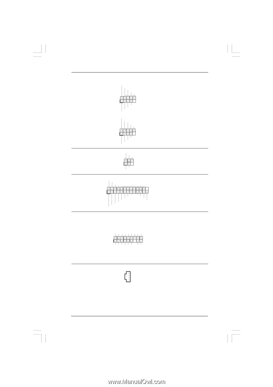
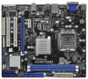
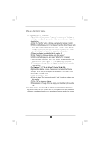
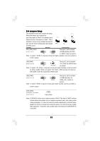
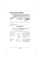
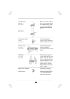
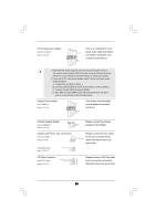
USB 2.0 Headers (9-pin USB6_7) (see p.11 No. 20) (9-pin USB4_5) (see p.11 No. 21) Infrared Module Header (5-pin IR1) (see p.11 No. 22) USB_PWR P-7 P+7 GND DUMMY 1 GND P+6 P-6 USB_PWR USB_PWR P-5 P+5 GND DUMMY 1 GND P+4 P-4 USB_PWR IRTX +5V DUMMY 1 GND IRRX Besides three default USB 2.0 ports on the I/O panel, there are two USB 2.0 headers on this motherboard. Each USB 2.0 header can support two USB 2.0 ports. This header supports an optional wireless transmitting and receiving infrared module. Print Port Header (25-pin LPT1) (see p.11 No. 23) TPM Header (17-pin TPM1) (see p.11 No. 7) AFD# ERROR# PINIT# SLIN# GND 1 SPD7 SPD6 ACK# SPD5 BUSY SPD4 PE SPD3 SLCT SPD2 SPD1 SPD0 STB# GND SMB_CLK_MAIN SMB_DATA_MAIN LAD2 LAD1 GND S_PWRDWN# SERIRQ# GND 1 PCICLK FRAME PCIRST# LAD3 +3V LAD0 +3VSB GND Internal Audio Connectors (4-pin CD1) (CD1: see p.11 No. 28) CD-L GND GND CD-R CD1 This is an interface for print port cable that allows convenient connection of printer devices. This connector supports a Trusted Platform Module (TPM) system, which can securely store keys, digital certificates, passwords, and data. A TPM system also helps enhance network security, protects digital identities, and ensures platform integrity. This connector allows you to receive stereo audio input from sound sources such as a CD-ROM, DVD-ROM, TV tuner card, or MPEG card. 24
-
 1
1 -
2
-
3
-
4
-
5
-
6
-
7
-
8
-
9
-
10
-
11
-
12
-
13
-
14
-
15
-
16
-
17
-
18
-
 19
19 -
 20
20 -
 21
21 -
 22
22 -
 23
23 -
 24
24 -
 25
25 -
 26
26 -
 27
27 -
 28
28 -
 29
29 -
30
-
31
-
32
-
33
-
34
-
35
-
36
-
37
-
38
-
39
-
40
-
41
-
42
-
43
-
44
-
45
-
46
-
47
-
48
-
49
-
50
-
51
-
52
-
53
-
54
 |
 |