ASRock H110M-STX User Manual
ASRock H110M-STX Manual
 |
View all ASRock H110M-STX manuals
Add to My Manuals
Save this manual to your list of manuals |
ASRock H110M-STX manual content summary:
- ASRock H110M-STX | User Manual - Page 1
- ASRock H110M-STX | User Manual - Page 2
change without notice, and should not be constructed as a commitment by ASRock. ASRock assumes no responsibility for any errors or omissions that may appear in CALIFORNIA, USA ONLY The Lithium battery adopted on this motherboard contains Perchlorate, a toxic substance controlled in Perchlorate Best - ASRock H110M-STX | User Manual - Page 3
if the goods fail to be of acceptable quality and the failure does not amount to a major failure. If you require assistance please call ASRock Tel : +886-2-28965588 ext.123 (Standard International call charges apply) The terms HDMI™ and HDMI High-Definition Multimedia Interface, and the HDMI logo - ASRock H110M-STX | User Manual - Page 4
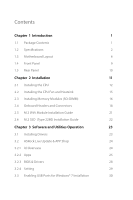
18 2.5 M.2 WiFi Module Installation Guide 21 2.6 M.2 SSD (Type 2280) Installation Guide 22 Chapter 3 Software and Utilities Operation 23 3.1 Installing Drivers 23 3.2 ASRock Live Update & APP Shop 24 3.2.1 UI Overview 24 3.2.2 Apps 25 3.2.3 BIOS & Drivers 28 3.2.4 Setting 29 - ASRock H110M-STX | User Manual - Page 5
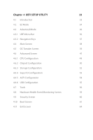
Chapter 4 UEFI SETUP UTILITY 33 4.1 Introduction 33 4.2 EZ Mode 34 4.3 Advanced Mode 36 4.3.1 UEFI Menu Bar 36 4.3.2 Navigation Keys 37 4.4 Main Screen 38 4.5 OC Tweaker Screen 39 4.6 Advanced Screen 47 4.6.1 CPU Configuration 48 4.6.2 Chipset Configuration 50 4.6.3 Storage - ASRock H110M-STX | User Manual - Page 6
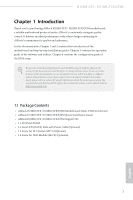
http://www.asrock.com. 1.1 Package Contents • ASRock H110M-STX / H110M-STX/COM Motherboard (Mini-STX Form Factor) • ASRock H110M-STX / H110M-STX/COM Quick Installation Guide • ASRock H110M-STX / H110M-STX/COM Support CD • 1 x I/O Panel Shield • 2 x Serial ATA(SATA) Data with Power Cable (Optional - ASRock H110M-STX | User Manual - Page 7
1.2 Specifications Platform CPU Chipset • Mini-STX Form Factor • Supports 6th Generation Intel® CoreTM i7/i5/i3/Pentium®/ Celeron® Processors (Socket 1151) • Supports CPU up to 65W • Supports Intel® Turbo Boost 2.0 Technology • Intel® H110 Memory • Dual Channel DDR4 Memory Technology • 2 x DDR4 - ASRock H110M-STX | User Manual - Page 8
-STX / H110M-STX/COM • Supports DisplayPort 1.2 with max. resolution up to 4K x 2K (4096x2304) @ 60Hz • Supports Auto Lip Sync, Deep Color (12bpc), xvYCC and HBR (High Bit Rate Audio) with HDMI Port (Compliant HDMI monitor is required) • Supports Accelerated Media Codecs: HEVC, VP8, VP9 • Supports - ASRock H110M-STX | User Manual - Page 9
the ISO file is required. Please refer to page 30 or more detailed instructions. * For the updated Windows® 10 driver, please visit ASRock's website for details: http://www.asrock.com Certifications • FCC, CE, WHQL, BSMI, RCM • ErP/EuP ready (ErP/EuP ready power supply is required) English 4 - ASRock H110M-STX | User Manual - Page 10
responsible for possible damage caused by overclocking. Mini-STX Chassis Support List Vendor SilverStone Technology Inc. AKasa Model VT01S A-STX04-A1B / A-STX04-M1B For the latest updates of Mini-STX chassis support list, please visit our website for details: http://www.asrock.com English 5 - ASRock H110M-STX | User Manual - Page 11
1.3 Motherboard Layout 12 DC Jack DP1 HDMI1 Audio CODEC VGA1 USB 2.0 T: USB3 Top: USB 3.0 RJ-45 B: USB4 9 1 CI1 H110M-STX CPU_FAN2 RoHS DDR4_A1 DDR4_B1 3 CPU_FAN1 1 4 LPC1 SPEAKER1 USB_5_6 1 5 1 COM1 6 1 Mic In 7 USB 3.0 USB_2 Intel Chipset M2_1_CT1 BIOS ROM M2_2_CT1 Super - ASRock H110M-STX | User Manual - Page 12
H110M-STX / H110M-STX/COM CMOS Battery SATA3 10 SATA3 11 12 7 English - ASRock H110M-STX | User Manual - Page 13
CPU Fan Connector (CPU_FAN1) 4 LPC Debug Header (LPC1) 5 USB 2.0 Header (USB_5_6) 6 Internal Speaker Header (SPEAKER1) 7 COM Port Header (COM1) (for H110M-STX/COM only) 8 System Panel Header (PANEL1) 9 Chassis Intrusion Header (CI1) 10 SATA3 Connector (SATA1) 11 SATA3 Connector (SATA2) 12 Clear CMOS - ASRock H110M-STX | User Manual - Page 14
1.4 Front Panel H110M-STX / H110M-STX/COM 1 2 3 4 No. Description 1 Headphone/Headset Jack (AUDIO1) 2 USB 3.0 Type-A Port (USB_1) No. Description 3 USB 3.0 Type-C Port (USB3_2) 4 Microphone Input (AUDIO2) English 9 - ASRock H110M-STX | User Manual - Page 15
1.5 Rear Panel 7 1 2 3 4 5 6 No. Description 1 DC Jack (Supports 19V Power Adapters) 2 Display Port 3 HDMI Port No. Description 4 D-Sub Port 5 USB 2.0 Port (USB_3) 6 USB 3.0 Port (USB_4) 7 LAN RJ-45 Port* * There are two LEDs on each - ASRock H110M-STX | User Manual - Page 16
H110M-STX / H110M-STX/COM Chapter 2 Installation This is a Mini-STX form factor motherboard. Before you install the motherboard, study the configuration of your chassis to ensure that the motherboard fits into it. Pre-installation Precautions Take note of the following precautions before you install - ASRock H110M-STX | User Manual - Page 17
socket. Do not force to insert the CPU into the socket if above situation is found. Otherwise, the CPU will be seriously damaged. 2. Unplug all power cables before installing the CPU. 1 A B 2 12 English - ASRock H110M-STX | User Manual - Page 18
H110M-STX / H110M-STX/COM 3 4 5 13 English - ASRock H110M-STX | User Manual - Page 19
Please save and replace the cover if the processor is removed. The cover must be placed if you wish to return the motherboard for after service. 14 English - ASRock H110M-STX | User Manual - Page 20
H110M-STX / H110M-STX/COM 2.2 Installing the CPU Fan and Heatsink 1 2 CPU_FAN English 15 - ASRock H110M-STX | User Manual - Page 21
allowed to install a DDR, DDR2 or DDR3 memory module into a DDR4 slot; otherwise, this motherboard and SO-DIMM may be damaged. The SO-DIMM only fits in one correct orientation. It will cause permanent damage to the motherboard and the SO-DIMM if you force the SO-DIMM into the slot at - ASRock H110M-STX | User Manual - Page 22
H110M-STX / H110M-STX/COM 1 2 3 17 English - ASRock H110M-STX | User Manual - Page 23
jumper caps over the headers and connectors will cause permanent damage to the motherboard. System Panel Header (9-pin PANEL1) (see p.4, No. 8) PLED+ PLEDPWRBTN# GND 1 GND RESET# GND HDLEDHDLED+ Connect the power switch, reset switch and system status indicator on the chassis to this header - ASRock H110M-STX | User Manual - Page 24
H110M-STX / H110M-STX/COM GND These two SATA3 connectors support SATA data cables for internal storage devices with up to 6.0 Gb/s data transfer GND P+ PUSB_PWR 1 There is one header on this motherboard. This USB 2.0 header can support two ports. CPU Fan Connector 1 (4-pin CPU_FAN1) 2 - ASRock H110M-STX | User Manual - Page 25
CPU Fan Connector (5-pin CPU_FAN2) (see p.4, No. 1) GND GND FAN_VOLTAGE FAN_SPEED FAN_SPEED_CONTROL This motherboard provides a 5-Pin CPU fan connector. This connector supports Intel® 1L Thermal Modules. Serial Port Header (for H110M-STX/COM only) (9-pin COM1) (see p.4, No. 7) RI RTS GND TXD DCD - ASRock H110M-STX | User Manual - Page 26
H110M-STX / H110M-STX/COM 2.5 M.2 WiFi Module Installation Guide 1. Insert the WiFi Module Card into the M.2 Slot for WiFi + BT Module. 2. Tighten the screw to secure the WiFi Module Card to the motherboard. 3. Attach the SMA Wi-Fi Antenna Cables to the WiFi Module. 21 English - ASRock H110M-STX | User Manual - Page 27
2.6 M.2 SSD (Type 2280) Installation Guide 1. Locate the M.2 slot on the motherboard. 2. Carefully insert the M.2 SSD into the slot. 3. Tighten the screw to secure the M.2 SSD to the motherboard. 22 English - ASRock H110M-STX | User Manual - Page 28
H110M-STX / H110M-STX/COM Chapter 3 Software and Utilities Operation 3.1 Installing Drivers The Support CD that comes with the motherboard contains necessary drivers and useful utilities that enhance the motherboard's features. Running The Support CD To begin using the support CD, insert the CD into - ASRock H110M-STX | User Manual - Page 29
install various apps and support utilities, such as USB Key, XFast LAN, XFast RAM and more. With ASRock APP Shop, you can optimize your system and keep your motherboard up to date simply with a few clicks. Double-click utility. on your desktop to access ASRock Live Update & APP Shop *You need - ASRock H110M-STX | User Manual - Page 30
H110M-STX / H110M-STX/COM 3.2.2 Apps When the "Apps" tab is selected, you will see all the available up and down to see more apps listed. You can check the price of the app and whether you have already intalled it or not. - The red icon displays the price or "Free" if the app is free of charge. - The - ASRock H110M-STX | User Manual - Page 31
Step 3 If you want to install the app, click on the red icon to start downloading. Step 4 When installation completes, you can find the green "Installed" icon appears on the upper right corner. English To uninstall it, simply click on the trash can icon . *The trash icon may not appear for - ASRock H110M-STX | User Manual - Page 32
H110M-STX / H110M-STX/COM Upgrading an App You can only upgrade the apps you have already installed. When there is an available new version for your app, you - ASRock H110M-STX | User Manual - Page 33
3.2.3 BIOS & Drivers Installing BIOS or Drivers When the "BIOS & Drivers" tab is selected, you will see a list of recommended or critical updates for the BIOS or drivers. Please update them all soon. Step 1 Please check the item information before update. Click on Step 2 to see more details. - ASRock H110M-STX | User Manual - Page 34
H110M-STX / H110M-STX/COM 3.2.4 Setting In the "Setting" page, you can change the language, select the server location, and determine if you want to automatically run the ASRock Live Update & APP Shop on Windows startup. 29 English - ASRock H110M-STX | User Manual - Page 35
7 inbox drivers, users may find it difficult to install Windows 7 operating system because the USB ports on their motherboard won't work drivers packed into the ISO file. Requirements • A Windows® 7 installation disk or USB drive • A Windows® PC • Win7 USB Patcher (included in the ASRock Support - ASRock H110M-STX | User Manual - Page 36
H110M-STX / H110M-STX/COM Instructions Step 1 Insert the Windows® 7 installation disk or USB drive to your system. Step 2 Extract the tool (Win7 USB Patcher) and launch it. Step 3 Select "Create a - ASRock H110M-STX | User Manual - Page 37
you are able to install Windows® 7 on Braswell or Skylake with the new burned CD. Or please use the patched ISO image to make an OS USB drive to install the - ASRock H110M-STX | User Manual - Page 38
H110M-STX / H110M-STX/COM Chapter 4 UEFI SETUP UTILITY 4.1 Introduction This section explains how to use the UEFI SETUP UTILITY to configure your system. You may run the UEFI SETUP UTILITY by pressing or right after you power on the computer, otherwise, the Power being updated, the - ASRock H110M-STX | User Manual - Page 39
current status. You can check the most crucial information of your system, such as CPU speed, DRAM frequency, SATA information, fan speed, etc. Press or click the "Advanced Mode" button at the upper right corner of the screen to switch to "Advanced Mode" for more options. H110M-STX: 34 English - ASRock H110M-STX | User Manual - Page 40
H110M-STX/COM: H110M-STX / H110M-STX/COM No. Function 1 Help 2 Load UEFI Defaults 3 Save Changes and Exit 4 Discard Changes 5 Change Language 6 Switch to Advanced Mode 35 English - ASRock H110M-STX | User Manual - Page 41
4.3 Advanced Mode The Advanced Mode provides more options to configure the BIOS settings. Refer to the following sections for the detailed configurations. To access the EZ Mode, press or click the "EZ Mode" button at the - ASRock H110M-STX | User Manual - Page 42
H110M-STX / H110M-STX/COM 4.3.2 Navigation Keys Use < > key or < > key to choose among the selections on the menu bar, and use < > key or < > key to move the cursor - ASRock H110M-STX | User Manual - Page 43
4.4 Main Screen When you enter the UEFI SETUP UTILITY, the Main screen will appear and display the system overview. H110M-STX: H110M-STX/COM: English My Favorite 38 Display your collection of BIOS items. Press F5 to add/remove your favorite items. - ASRock H110M-STX | User Manual - Page 44
H110M-STX / H110M-STX/COM 4.5 OC Tweaker Screen In the OC Tweaker screen, you can set up overclocking features. Because the UEFI software is constantly being updated, the between multiple frequencies and voltage points for better power saving and heat dissipation. Intel Speed Shift Technology - ASRock H110M-STX | User Manual - Page 45
after a period of time. A lower limit can protect the CPU and save power, while a higher limit may improve performance. Long Duration Maintained Configure the period of settings. DRAM Frequency If [Auto] is selected, the motherboard will detect the memory module(s) inserted and assign the - ASRock H110M-STX | User Manual - Page 46
H110M-STX / H110M-STX/COM RAS# to CAS# Delay and Row Precharge (tRCDtRP) RAS# to CAS# Delay : The number of clock cycles required between the opening of a row of - ASRock H110M-STX | User Manual - Page 47
Read to Precharge (tRTP) The number of clocks that are inserted between a read command to a row precharge command to the same rank. Four Activate Window (tFAW) The time window in which four activates are allowed the same rank. CAS Write Latency (tCWL) Configure CAS Write Latency. Third Timing tREFI - ASRock H110M-STX | User Manual - Page 48
H110M-STX / H110M-STX/COM tRDWR_dd Configure between module read to write delay. tWRRD_sg Configure between module write to read delay. tWRRD_dg Configure between module write to read delay. - ASRock H110M-STX | User Manual - Page 49
IO-L (CH A) Configure IO latency for channel A. IO-L (CH B) Configure IO latency for channel B. IO-L Offset (CH A) Configure IO latency offset for channel A. IO-L Offset (CH B) Configure IO latency offset for channel B. RFR Delay (CH A) Configure RFR Delay for Channel A. RFR Delay (CH B) Configure - ASRock H110M-STX | User Manual - Page 50
H110M-STX / H110M-STX/COM twRPDEN Configure twRPDEN. OREF_RI Configure OREF_RI. tREFIx9 Configure tREFIx9. txSDLL Configure txSDLL. txs_offset Configure txs_offset. tZQOPER Configure tZQOPER. tMOD Configure tMOD. ZQCS_period Configure ZQCS_period. - ASRock H110M-STX | User Manual - Page 51
settings. The default is [Auto]. ODT NOM (CH B) Use this to change ODT (CH B) Auto/Manual settings. The default is [Auto]. MRC Fast Boot Enable Memory Fast Boot to skip DRAM memory training for booting faster. Dll Bandwidth 0 Configure the Dll - ASRock H110M-STX | User Manual - Page 52
H110M-STX / H110M-STX/COM 4.6 Advanced Screen In this section, you may set the configurations for the following items: CPU Configuration, Chipset Configuration, Storage Configuration, Super IO Configuration, ACPI - ASRock H110M-STX | User Manual - Page 53
Active Processor Cores Select the number of cores to enable in each processor package. CPU C States Support Enable CPU C States Support for power saving. It is recommended to keep C3, C6 and C7 all enabled for better power saving. Enhanced Halt State (C1E) Enable Enhanced Halt State (C1E) for lower - ASRock H110M-STX | User Manual - Page 54
H110M-STX / H110M-STX/COM CPU Thermal Throttling Enable CPU internal thermal control mechanisms to keep the CPU from requested cache line. Enable for better performance. Software Guard Extensions (SGX) Enable or disable the support for Intel® Software Guard Extensions (Intel® SGX). 49 English - ASRock H110M-STX | User Manual - Page 55
, security, isolation, and I/O performance. PCIE ASPM Support This option enables/disables the ASPM support for all CPU downstream devices. PCH PCIE ASPM Support This option enables/disables the ASPM support for all PCH PCIE devices. DMI ASPM Support This option enables/disables the control of ASPM - ASRock H110M-STX | User Manual - Page 56
H110M-STX / H110M-STX/COM PCH DMI ASPM Support This option enables/disables the ASPM support for all PCH DMI devices. IOAPIC 24-119 Entries Enable or disable IOAPIC 24-119 Entries to expand your PIROI-PIROX. Share Memory Configure the - ASRock H110M-STX | User Manual - Page 57
4.6.3 Storage Configuration SATA Controller(s) Enable/disable the SATA controllers. SATA Aggressive Link Power Management SATA Aggressive Link Power Management allows SATA devices to enter a low power state during periods of inactivity to save power. It is only supported by AHCI mode. Hard Disk - ASRock H110M-STX | User Manual - Page 58
4.6.4 Super IO Configuration H110M-STX / H110M-STX/COM Serial Port (for H110M-STX/COM only) Enable or disable the Serial port. Serial Port Address (for H110M-STX/COM only) Select the address of the Serial port. 53 English - ASRock H110M-STX | User Manual - Page 59
by the real time clock alarm. Set it to By OS to let it be handled by your operating system. USB Keyboard/Remote Power On Allow the system to be waked up by an USB keyboard or remote controller. USB Mouse Power On Allow the system to be waked up by an USB - ASRock H110M-STX | User Manual - Page 60
H110M-STX / H110M-STX/COM Legacy USB Support Enable or disable Legacy OS Support for USB 2.0 devices. If you encounter USB compatibility issues it is recommended to disable legacy USB support. Select UEFI Setup Only to support USB devices under the UEFI setup and Windows/Linux operating - ASRock H110M-STX | User Manual - Page 61
. UEFI Tech Service Contact ASRock Tech Service if you are having trouble with your PC. Please setup network configuration before using UEFI Tech Service. Easy Driver Installer For users that don't have an optical disk drive to install the drivers from our support CD, Easy Driver Installer is - ASRock H110M-STX | User Manual - Page 62
H110M-STX / H110M-STX/COM Boot Manager Boot Manager is specifically designed for the dual OS platform/multi-OS platform ASRock Internet Flash downloads and updates the latest UEFI firmware version from our servers for you. Please setup network configuration before using Internet Flash. *For BIOS - ASRock H110M-STX | User Manual - Page 63
Network Configuration Use this to configure internet connection settings for Internet Flash. Internet Setting Enable or disable sound effects in the setup utility. UEFI Download Server Select a server to download the UEFI firmware. 58 English - ASRock H110M-STX | User Manual - Page 64
H110M-STX / H110M-STX/COM 4.8 Hardware Health Event Monitoring Screen This section allows you to monitor the status of the hardware on your system, including the parameters of the CPU temperature, motherboard temperature, fan speed and voltage. Fan-Tastic Tuning Select a fan mode for CPU Fan, or - ASRock H110M-STX | User Manual - Page 65
settings in the UEFI Setup Utility. Leave it blank and press enter to remove the password. Secure Boot Use this item to enable or disable support for Windows 8.1 Secure Boot. Intel(R) Platform Trust Technology Enable/disable Intel PTT in ME. Disable this option to use discrete - ASRock H110M-STX | User Manual - Page 66
H110M-STX/COM 4.10 Boot Screen This section displays the available devices on your system for you to configure the boot settings and the boot priority. Fast Boot Fast Boot minimizes your computer's boot time. In fast mode you may not boot from an USB storage device. Ultra Fast mode is only supported - ASRock H110M-STX | User Manual - Page 67
Full Screen Logo Enable to display the boot logo or disable to show normal POST messages. AddOn ROM Display Enable AddOn ROM Display to see the AddOn ROM messages or configure the AddOn ROM if you've enabled Full Screen Logo. Disable for faster boot speed. Boot Failure Guard If the computer fails to - ASRock H110M-STX | User Manual - Page 68
CSM (Compatibility Support Module) H110M-STX / H110M-STX/COM CSM Enable to launch the Compatibility Support Module. Please do not disable unless you're running a WHCK test. If you are using Windows 8.1 64-bit and all of your devices support UEFI, you may also disable CSM for faster boot speed. - ASRock H110M-STX | User Manual - Page 69
4.11 Exit Screen Save Changes and Exit When you select this option the following message, "Save configuration changes and exit setup?" will pop out. Select [OK] to save changes and exit the UEFI SETUP UTILITY. Discard Changes and Exit When you select this option the following message, "Discard - ASRock H110M-STX | User Manual - Page 70
H110M-STX / H110M-STX/COM Contact Information If you need to contact ASRock or want to know more about ASRock, you're welcome to visit ASRock's website at http://www.asrock.com; or you may contact your dealer for further information. For technical questions, please submit a support request form at
-
 1
1 -
 2
2 -
 3
3 -
 4
4 -
 5
5 -
 6
6 -
 7
7 -
8
-
9
-
10
-
11
-
12
-
13
-
14
-
15
-
16
-
17
-
18
-
19
-
20
-
21
-
22
-
23
-
24
-
25
-
26
-
27
-
28
-
29
-
30
-
31
-
32
-
33
-
34
-
35
-
36
-
37
-
38
-
39
-
40
-
41
-
42
-
43
-
44
-
45
-
46
-
47
-
48
-
49
-
50
-
51
-
52
-
53
-
54
-
55
-
56
-
57
-
58
-
59
-
60
-
61
-
62
-
63
-
64
-
65
-
66
-
67
-
68
-
69
-
70
 |
 |