ASRock H110M-STX User Manual - Page 25
for H110M-STX/COM, LPC Debug Header
 |
View all ASRock H110M-STX manuals
Add to My Manuals
Save this manual to your list of manuals |
Page 25 highlights
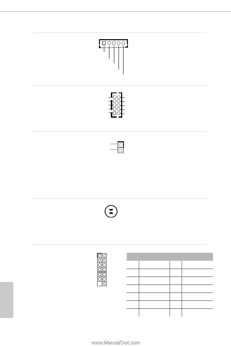
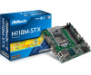
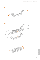
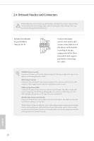
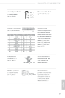
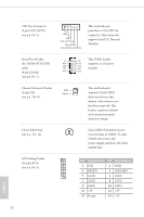
CPU Fan Connector (5-pin CPU_FAN2) (see p.4, No. 1) GND GND FAN_VOLTAGE FAN_SPEED FAN_SPEED_CONTROL This motherboard provides a 5-Pin CPU fan connector. This connector supports Intel® 1L Thermal Modules. Serial Port Header (for H110M-STX/COM only) (9-pin COM1) (see p.4, No. 7) RI RTS GND TXD DCD 1 This COM1 header NC CTS supports a serial port DSR DTR module. RXD Chassis Intrusion Header (2-pin CI1) (see p.4, No. 9) GND Signal Clear CMOS Pad (see p.5, No. 12) LPC Debug Header 1 (13-pin LPC1) (see p.4, No. 4) This motherboard 1 supports CASE OPEN detection feature that detects if the chassis cove has been removed. This feature requires a chassis with chassis intrusion detection design. Clear CMOS Pad allows you to clear the data in CMOS. To clear CMOS, disconnect the power supply and short the Clear CMOS Pad. PIN Signal Name PIN Signal Name 1 CLK 2 GND 3 RESET# 4 LFRAME# 5 LAD0 6 LAD1 7 LAD2 8 LAD3 9 LAD3 10 LAD3 11 +3V 12 +3V 13 No pin 14 +3V English 20
-
 1
1 -
2
-
3
-
4
-
5
-
6
-
7
-
8
-
9
-
10
-
11
-
12
-
13
-
14
-
15
-
16
-
17
-
18
-
19
-
 20
20 -
 21
21 -
 22
22 -
 23
23 -
 24
24 -
 25
25 -
 26
26 -
 27
27 -
 28
28 -
 29
29 -
 30
30 -
31
-
32
-
33
-
34
-
35
-
36
-
37
-
38
-
39
-
40
-
41
-
42
-
43
-
44
-
45
-
46
-
47
-
48
-
49
-
50
-
51
-
52
-
53
-
54
-
55
-
56
-
57
-
58
-
59
-
60
-
61
-
62
-
63
-
64
-
65
-
66
-
67
-
68
-
69
-
70
 |
 |